

PANEL FURNITURE DRILLING
Wood Multi Boring Machines for Furniture and Cabinet Panels
Wood multi boring machines produce coordinated hole patterns in compatible furniture and cabinet panels using multiple drilling spindles or heads. Correct selection depends on the panel material and dimensions hole layout diameter depth spacing face and edge operations references tooling batch mix output extraction utilities and line integration requirements.
The panel is referenced and clamped before the selected drilling heads advance according to the approved setup or program. Multiple spindles can create several compatible holes in one controlled cycle when the installed spacing tooling travel and panel support match the drilling pattern. Configurations may include horizontal or vertical boring units adjustable rows digital positioning CNC control automatic loading barcode input or production line communication. These functions and the exact spindle count spacing capacity accuracy and cycle time must be confirmed from approved documents for the selected machine
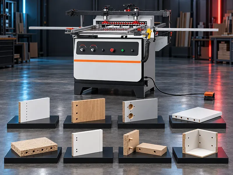
What a multi boring machine does
The machine positions one or more drilling spindles to create an approved pattern of holes in a compatible wood panel or component. Multiple holes may be produced in one cycle when their locations match the installed head arrangement.
The machine should be selected from the product drilling map and assembly method. The machine category alone does not prove the number of holes dimensions accuracy or line productivity.
Furniture and cabinet applications
Potential applications include cabinet sides shelves doors partitions carcass parts drawer components office furniture kitchen units wardrobes shelving systems and selected knock down furniture parts.
Hole patterns may support dowels hinges connectors shelves assembly hardware and selected fittings. Every pattern must be reviewed against the hardware supplier drawing and finished product design.
Panel materials and condition
Potential materials may include compatible medium density fibreboard particleboard plywood laminated panels melamine faced boards and selected solid wood components when approved for the machine tooling holding and extraction system.
Material thickness density coating adhesive layers moisture flatness warp edge condition and internal contamination affect drill load breakout chip evacuation tool life and assembly fit.
Hole map and machining data
Provide a drawing or digital drilling map showing panel datums face and edge orientation hole coordinates diameters depths through or blind condition countersinks counterbores and hardware references.
The data should identify mirrored parts left and right versions grain direction finished faces tolerance zones and any holes completed by another machine.
Horizontal and vertical drilling
Vertical heads may drill panel faces while horizontal heads may drill selected edges according to the installed arrangement. Some machines combine directions while others require separate setups or machines.
Confirm head directions quantity travel working sequence interference zones tool projection and whether face and edge operations can occur in the same clamping.
Boring heads rows and spindle spacing
A boring head may contain a row or grid of spindles with fixed or adjustable relationships depending on the design. Only selected spindles may be activated for a given pattern.
Verify head quantity spindle count center spacing rotation directions activation method adjustment range service access and compatibility with the required furniture drilling system.
Drill bits and toolholders
Tooling may include brad point drills dowel drills through hole drills countersinks counterbores or approved specialist tools. Diameter length cutting geometry rotation hand and holder interface should match the spindle panel and hole requirement.
Confirm tool capacity shank interface projection depth setting replacement sharpening life criteria runout basis and approved left and right rotation tools.
Panel references positioning and squaring
Stable datums are required for panel length width face edge and corner references. Stops fences measuring systems or programmed axes may establish the drilling position according to the machine configuration.
Confirm reference surfaces positioning travel squaring method compensation minimum and maximum part sizes mirrored part handling and protection of finished surfaces.
Clamping and panel support
The panel should be held flat and securely against approved references before tool movement. Clamps should resist drilling forces without marking crushing lifting or shifting the panel.
Verify clamp quantity location pressure control sensors support tables rollers or air flotation and safe behavior with narrow short flexible warped or coated panels.
Depth control and breakout prevention
Blind holes require controlled depth while through holes need suitable support and tool projection. Correct cutting data sharp tools backing support and chip evacuation can help reduce breakout and surface damage.
Confirm depth adjustment resolution calibration compensation panel thickness sensing backing method sacrificial surfaces and separate settings for different tools and materials.
Manual digital and CNC configurations
Manual or mechanically adjusted machines may suit stable repeated patterns when setup and capacity match the product. Digital positioning or CNC systems may support faster changeover and varied programs when their functions are verified.
Confirm axes control type interface language program capacity recipe protection file formats barcode functions network options diagnostics backups permissions and change control.
Barcode and production line integration
A barcode system may call an approved program from production data when the scanner software labels and database are correctly integrated. Automated lines may exchange part identity dimensions status and routing information.
Verify communication protocol data owner field mapping error handling duplicate prevention offline operation cybersecurity permissions traceability and interfaces with cutting edging assembly and production software.
Chip extraction and work area cleaning
Drilling produces chips and fine dust around tools holes heads and support surfaces. Accumulation can affect depth references clamps mechanisms tool cooling air quality and fire risk.
Confirm extraction hoods ports airflow pressure ducting filtration waste handling dust classification cleaning access grounding and fire controls for every approved panel material.
Hole quality and inspection
Inspection may cover diameter depth position spacing perpendicularity edge distance alignment between face and edge holes breakout chipping burning surface marks and fit with dowels or hardware.
The quality plan should define datums tolerances gauges templates first panel approval sampling calibration tool wear correction limits traceability and treatment of nonconforming parts.
Production workflow
Begin with an approved product drawing hardware drilling map panel identification program or setup sheet tooling list references clamping extraction settings and inspection method. Verify guards interlocks sensors and emergency functions.
Run a sample panel inspect all critical holes and test hardware or assembly fit where required. Record approved corrections before releasing controlled batch production.
Cycle time and production planning
Total cycle time includes loading identification referencing clamping head positioning drilling retraction chip clearing repositioning unloading inspection program selection and changeover.
No production rate or efficiency claim should be published without a timed trial using the actual panel hole map tooling loading method staffing integration and quality criteria.
Safety and operating risks
Risks include rotating drills moving heads axes and panels clamp crushing pinch points tool breakage ejected chips dust noise electrical energy pneumatic energy unexpected automatic motion program errors and manual handling.
The machine requires approved guards interlocks emergency stops safe setup mode energy isolation controlled clamping extraction tool verification loading zones operator training supervision and a documented risk assessment.
Installation and commissioning
Site planning should cover delivery access floor condition leveling anchoring service clearance panel storage material flow loading and unloading support electrical and air supplies extraction ducting network access when approved lighting waste handling and maintenance access.
Commissioning should verify geometry references head alignment spindle rotation depth calibration clamps extraction programs interfaces guards interlocks emergency functions sample panels training documents and an agreed acceptance trial.
Maintenance and lifecycle support
Preventive maintenance should follow approved schedules for spindles heads bearings guides screws drives clamps stops tables lubrication extraction sensors electrical cabinet controls scanners guards interlocks and emergency devices.
Agree drill supply sharpening and replacement criteria holders collets seals cylinders guides bearings filters lubricants calibration tools software backups licenses manuals training inspection records service responsibility and recommended spare parts.
How to select the correct machine
Provide product drawings drilling maps hardware details panel materials thickness dimensions weight face and edge operations hole diameters depths spacing quantities batch mix tolerances and target output.
Also define head directions spindle arrangement tooling setup or CNC needs barcode and line integration extraction electrical and air supply floor layout handling staffing maintenance capability and acceptance tests.
Technical information to verify
Approved documents must confirm panel length width thickness and weight ranges head quantity orientation and travel spindle count spacing speed rotation activation and tool interface together with hole diameter and depth limits.
Positioning axes accuracy test basis clamps tables extraction demand electrical and air requirements control software barcode and network functions dimensions weight floor loading noise basis guards safety functions standard equipment options manuals training warranty service and acceptance method also require confirmation.
Limitations and publishing status
The supplied title does not verify material compatibility head quantity spindle count spacing face and edge capability CNC functions barcode support line integration capacity accuracy speed cycle time output extraction or safety configuration.
Publication requires the approved exact datasheet machine layout head and spindle map tooling list control and software description electrical and pneumatic drawings extraction and safety documents sample panel results approved image technical review staging review and final content approval.
Technical review and next step
Send product and drilling drawings hardware references panel data hole diameters depths spacing quantities tolerances output utilities and factory layout for technical review.
The review should define the suitable heads spindle arrangement tools references clamping control barcode integration extraction inspection acceptance trial installation training maintenance consumables and spare parts scope.
Questions we are asked
What is a wood multi boring machine?
It is a woodworking machine that uses multiple drilling spindles or heads to create an approved pattern of holes in compatible panels and components.
Can it drill panel faces and edges?
Only configurations with the required verified vertical and horizontal heads travels tools and clamping can complete the selected face and edge operations.
Is the spindle spacing adjustable?
Spacing may be fixed adjustable or generated by CNC axes depending on the machine design. The required drilling map must be compared with the approved spindle layout.
Can it connect to a furniture production line?
Line integration may be possible when the machine control software barcode data protocol loading system and safety interfaces are included and validated.
What information is needed for selection?
Provide product and drilling drawings hardware references panel data hole diameters depths spacing quantities tolerances output utilities and factory layout.
Tell us the part you need to make
An engineer reads every request. Usually the same working day.
Related
- CNC WOOD ROUTER CNC routing solutions for cutting, drilling, engraving and machining suitable wood panels and furniture components.
- CNC ROUTER WITH ROTARY A CNC router equipped with a rotary attachment or axis for machining suitable cylindrical and shaped workpieces. Selection depends on the part geometry, material, dimensions, required operations, accuracy, and production volume.
- Automatic Edge Banding Machines Automatic edge banding machines apply and finish compatible edge material on straight panel edges through a controlled production sequence. Correct selection depends on the panel material dimensions edge tape adhesive production volume finish requirement installed processing units utilities and extraction system.