

CNC Woodworking Solutions
CNC WOOD ROUTER
CNC routing solutions for cutting, drilling, engraving and machining suitable wood panels and furniture components.
A CNC WOOD ROUTER uses a computer-controlled spindle and cutting tools to machine programmed shapes, holes, pockets, grooves and profiles in suitable woodworking materials.
Machine selection depends on the material, panel or workpiece dimensions, thickness, required operations, production volume, tooling, holding method and available utilities. Explore our woodworking machines or send your drawings for technical selection.
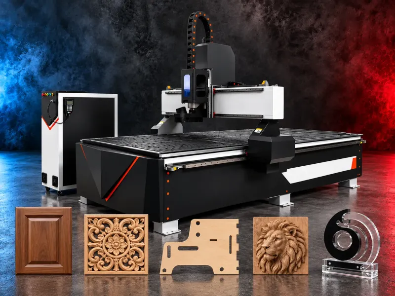
Typical Applications:
- Cabinet and furniture components
- MDF, plywood and particleboard components when approved for the selected model
- Doors, fronts, shelves and interior panels
- Decorative panels and carved elements
- Cutting profiles, pockets, grooves and openings
- Drilling and routing assembly features
- Nested production from suitable sheet materials
- Patterns, prototypes and customised wooden components
- Signage and display components when compatible with the selected machine
How Does a CNC Wood Router Work?:
A CNC wood router follows a programmed toolpath created using suitable CAD/CAM software. The control system moves the spindle along the machine axes while the cutting tool performs the required routing, drilling, profiling or engraving operations.
The workpiece may be held using a vacuum table, clamps, pods or another approved system. The suitable holding method depends on the material, part size, machining forces and machine configuration.
Actual machining quality and output depend on the selected model, spindle, tooling, material condition, toolpath, feed rates, workholding, extraction system and operator setup.
How to Select the Right CNC Wood Router:
- 1. Define the material type, density, condition and thickness range.
- 2. Provide the maximum panel or workpiece dimensions and weight.
- 3. Identify the required cutting, routing, drilling and engraving operations.
- 4. Confirm whether production requires nesting, individual components or three-dimensional machining.
- 5. Define the required edge quality, tolerance and surface finish.
- 6. Select the working area and vertical clearance required by the parts.
- 7. Match the spindle, tool interface and speed range to the application.
- 8. Determine whether automatic tool changing or a drilling unit is required.
- 9. Review the table type, vacuum capacity and workholding method.
- 10. Confirm CAD/CAM software, file formats and programming requirements.
- 11. Review dust extraction, compressed air, electrical supply and site conditions.
- 12. Define production volume, material handling and automation requirements.
Technical Data to Verify:
- X, Y and Z working areas
- Maximum workpiece dimensions and thickness
- Table type and number of vacuum zones
- Maximum permitted workpiece load
- Spindle power, torque and speed range
- Spindle cooling system
- Tool interface and collet system
- Automatic tool changer and number of positions
- Drilling unit and available drilling functions
- Number of controlled axes
- Cutting feed and rapid traverse rates
- Positioning accuracy and repeatability
- Axis drive and guide systems
- CNC control and compatible CAD/CAM software
- Supported programming and file formats
- Vacuum-pump capacity and requirements
- Dust-extraction connection and airflow requirements
- Compressed-air requirements
- Electrical supply and total connected power
- Machine dimensions, weight and installation requirements
All technical values and compatible materials must be taken from the latest official documentation for the selected brand and model.
Standard and Optional Equipment:
Depending on the selected model, equipment may include:
- CNC control system
- Air-cooled or liquid-cooled spindle
- Manual tool-changing system
- Automatic tool changer
- Vacuum table with separately controlled zones
- Vacuum pump
- Clamping or pod-based workholding system
- Dust-extraction hood and connections
- Drilling unit
- Oscillating-knife or specialised processing units
- Rotary-axis attachment
- Tool-length measuring sensor
- Automatic lubrication system
- CAD/CAM and nesting software
- Automatic loading, labelling and unloading systems
- Safety enclosure, light barriers or perimeter protection
Standard equipment, options, software licences, tools and accessories must be confirmed in the approved quotation.
Compatible Materials:
Material compatibility depends on the selected model, spindle, cutting tools, workholding and extraction system.
Typical woodworking applications may include solid wood, MDF, plywood, particleboard and laminated panels. Every material and thickness must be verified against the official machine documentation before approval.
Plastics, composites, aluminium or other non-wood materials must not be listed as compatible unless they are explicitly approved for the selected model and configuration.
Application Limits:
A CNC WOOD ROUTER is not automatically a replacement for a panel saw, edge-banding machine, wide-belt sander or specialised solid-wood machining centre.
Very small parts, porous sheets, warped panels or narrow components may require dedicated clamping, pods, fixtures or alternative processing methods.
Tool accessibility, vertical clearance, spindle capability and axis configuration limit the shapes and operations that can be completed in one setup.
Installation and Support:
- Application, drawing and material review
- Site layout and access assessment
- Floor, electrical and compressed-air review
- Vacuum and dust-extraction assessment
- Machine unloading and positioning requirements
- Installation, levelling and commissioning
- CNC control and CAD/CAM training
- Tooling and workholding recommendations
- Test machining using approved sample parts
- Preventive-maintenance planning
- Spare-parts and consumables support
- Warranty according to the approved quotation
Installation, training, software, tooling, service and warranty scope must be confirmed for the selected model and approved commercial offer.
Request a Technical Recommendation:
Send the part drawings, material type, dimensions, thickness range, required operations, tolerances and production volume to determine the appropriate working area, spindle, tooling, table, vacuum system and machine configuration.
Tell us the part you need to make
An engineer reads every request. Usually the same working day.
Related
- CNC ROUTER WITH ROTARY A CNC router equipped with a rotary attachment or axis for machining suitable cylindrical and shaped workpieces. Selection depends on the part geometry, material, dimensions, required operations, accuracy, and production volume.
- Automatic Edge Banding Machines Automatic edge banding machines apply and finish compatible edge material on straight panel edges through a controlled production sequence. Correct selection depends on the panel material dimensions edge tape adhesive production volume finish requirement installed processing units utilities and extraction system.
- Panel Saws for Wood Based Sheet Materials Panel saws divide compatible full size boards into accurately planned components for furniture cabinetry fit out and panel processing work. Machine selection depends on the panel material dimensions thickness cut pattern edge quality tolerance production volume blade system handling method dust extraction and required cutting functions.