

COMPLETE PANEL MACHINING IN ONE FLOW
CNC Six Sided Drilling and Routing Machine
A CNC six sided drilling machine processes furniture panels from the top bottom and four edges without repeated manual repositioning when the approved configuration supports the required operations. Correct selection depends on panel material dimensions hole patterns grooves routing details batch mix software tooling handling extraction utilities and finished accuracy.
The machine is designed for flexible panel production where different part files may follow one another in small or large batches. Automated referencing gripping and transfer help preserve part orientation while the drilling and routing units execute the programmed features. Typical applications include cabinet wardrobe kitchen office and custom furniture panels. The exact faces that can be processed tools included software interfaces and production performance must be confirmed from the approved technical documentation.
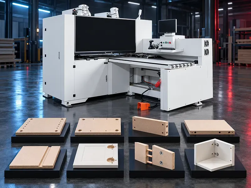
What the machine does
The machine receives a prepared furniture panel identifies its reference and positions it through the machining area. Drilling units and an approved routing spindle can create the programmed holes grooves recesses and contours according to the supplied configuration.
Processing several faces in one controlled flow can reduce manual turning and separate setups while supporting consistent references between features.
Meaning of six sided machining
Six sided machining refers to access to the top bottom and four panel edges through coordinated drilling heads positioning and workpiece handling. It does not mean that every possible feature can be produced on every face.
Tool direction clearance panel support and machine configuration determine which holes grooves or routed features are feasible.
Typical production workflow
A verified part file and panel identifier are prepared before loading. The panel is referenced gripped and moved through the programmed operations then discharged for inspection or the next production step.
Part orientation labels program revision and completed part routing should be controlled to prevent mirrored drilling mixed panels or missing operations.
Vertical drilling
Vertical drilling units create approved holes from the upper or lower panel surface according to the machine configuration. Common needs may include construction fittings shelf positions connectors and hardware locations.
Hole diameter depth spacing and breakthrough condition depend on the drawing drill type panel structure backing support and programmed parameters.
Horizontal edge drilling
Horizontal drills can machine selected panel edges for dowels connectors fasteners and approved joinery. Correct edge reference and panel stability are essential because small position errors can affect assembly.
Confirm available drill directions tool positions edge clearance minimum panel dimensions and compatibility with the intended joint system.
Grooving and routing
An approved routing spindle may create grooves recesses slots cutouts and simple contours within the configured travel and tooling limits. Routing can support back panel grooves hardware recesses and selected shaping tasks.
Confirm spindle functions tool interface speed range tool diameter depth and whether tool changing is manual or automatic for the offered machine.
Batch size one production
Automated program selection and flexible part handling can support mixed panel sequences where consecutive components are different. Practical performance depends on file preparation identification loading tool availability machining time and downstream sorting.
A batch size one claim should be evaluated using the actual product mix and a complete test from design data to finished labeled panels.
Panel materials and condition
Provide the board type thickness surface finish density core structure coating edge treatment and dimensional tolerance. Particleboard fiberboard plywood laminated panels and solid wood components behave differently during drilling and routing.
Panels should be flat clean and free from hidden metal or loose surface layers. Material suitability requires a verified sample and approved tooling.
Panel referencing and gripping
The handling system establishes the panel reference and moves the workpiece while maintaining access to the required faces. Grippers or clamps must hold securely without damaging the finished surface or colliding with programmed features.
Confirm gripping range repositioning logic clamp pressure reference sensors and rules for narrow short thin or flexible parts.
Software and production data
The machine requires accurate machining data that may come from approved design production or optimization software. File format post processor feature mapping part identification and network transfer must be compatible with the controller.
Verify software licenses interfaces barcode or label functions program simulation backup user permissions and revision control before approving the workflow.
Tooling and setup
Drills router tools collets holders and measuring devices must match the panel material hole geometry spindle interface and programmed speed. Tool length diameter condition and installed position should be controlled.
Prepare a documented tool list and setup for each product family and inspect the first part after tool replacement or program revision.
Accuracy and quality control
Finished quality should be judged from hole position diameter depth perpendicularity groove dimensions breakout edge finish and assembly fit against the approved drawing. Machine positioning alone does not account for tool wear panel variation or data errors.
Use calibrated gauges and an approved sample plan. Record corrections tool changes and rejected parts when traceability is required.
Dust extraction and waste handling
Drilling and routing create chips and fine dust that can affect hole quality sensors guides and fire risk. The extraction system must provide the approved airflow and connections at the active machining points.
Collection capacity filter maintenance duct cleaning and waste disposal should suit the panel material and production duty.
Safety and operator protection
The machine contains rotating tools automatic grippers moving axes and powered panel transfer. Guards monitored access emergency stops extraction and safe control functions should be provided according to the approved risk assessment.
Safe procedures must cover loading program setup tool changes first part testing unloading jam recovery cleaning and maintenance.
Installation and system integration
Site readiness should confirm floor condition electrical supply compressed air extraction network connection lighting material flow and maintenance clearance. Infeed and outfeed arrangements must suit panel sizes and downstream handling.
Integration with design software labels conveyors sorting or production management requires separate interface verification and an end to end test.
Training maintenance and lifecycle support
Training should cover programs file checks panel references tooling inspection quality control safe recovery extraction and daily care. Operators should understand how incorrect orientation or data affects every following assembly step.
Preventive maintenance should address drills router tools collets grippers guides drives lubrication sensors cables extraction hoses and safety devices. Prepare an approved spare parts and consumables plan.
How to select the correct machine
Start with panel drawings materials minimum and maximum sizes hole directions groove and routing features quantities batch mix tolerances software source labels and downstream process. Then define tooling handling extraction utilities and acceptance samples.
Selection should be based on representative parts and a verified digital workflow rather than the number of drilling faces alone.
Technical information requiring verification
Verify panel length width thickness and weight ranges. Also verify drilling head arrangement drill count spindle power and speed tool interface axes feed speed gripping system positioning accuracy cycle time extraction demand compressed air electrical load software interfaces dimensions and weight.
Confirm included tools software licenses guarding installation commissioning training warranty service scope spare parts and the agreed factory and site acceptance tests.
Publishing status
This page describes the machine category and selection logic. Exact capacities speeds accuracy productivity features software compatibility options standards and commercial commitments require an approved data sheet and technical review before publication.
Questions we are asked
What is a CNC six sided drilling machine?
It is a panel machining system that can access the top bottom and four edges for approved drilling and routing operations without repeated manual turning.
Can it drill all six faces in one pass?
The machine can coordinate access to six faces but the actual sequence and feasible features depend on tooling directions panel size gripping and the exact configuration.
Can it perform routing and grooving?
Routing and grooving may be supported when the machine includes an approved spindle tools and travel for the required features.
Is it suitable for mixed panel production?
It may support consecutive different parts when the software files identification tooling and material flow are correctly integrated and verified.
Which panel materials can be processed?
Compatibility depends on the approved board type thickness surface core structure tooling and required finish. A sample trial is required.
What information is needed for selection?
Provide panel drawings materials size range hole directions grooves routed features quantities batch mix tolerances software source labels extraction utilities and site layout.
Tell us the part you need to make
An engineer reads every request. Usually the same working day.
Related
- CNC WOOD ROUTER CNC routing solutions for cutting, drilling, engraving and machining suitable wood panels and furniture components.
- CNC ROUTER WITH ROTARY A CNC router equipped with a rotary attachment or axis for machining suitable cylindrical and shaped workpieces. Selection depends on the part geometry, material, dimensions, required operations, accuracy, and production volume.
- Automatic Edge Banding Machines Automatic edge banding machines apply and finish compatible edge material on straight panel edges through a controlled production sequence. Correct selection depends on the panel material dimensions edge tape adhesive production volume finish requirement installed processing units utilities and extraction system.