

AUTOMATED BUILT UP BEAM FABRICATION
Vertical H Beam Automatic Production Line
A vertical H beam automatic production line integrates plate positioning assembly welding straightening and conveying to manufacture built up steel beams through a controlled workflow. Correct selection depends on beam drawings material grades flange and web dimensions welding procedure output target quality requirements handling plan utilities and safety conditions.
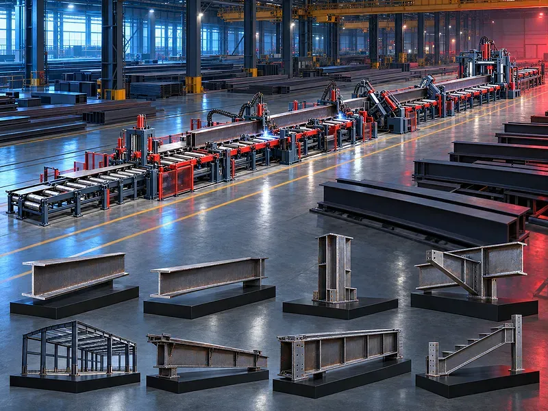
The line is intended to transform prepared web and flange plates into assembled H sections while reducing repeated crane handling between separate operations. A vertical arrangement supports controlled positioning of the plates as the beam progresses through the configured stations. The exact workflow may include assembly tack welding continuous welding flange correction transfer and discharge functions. Every function must be confirmed from the approved line configuration because equipment scope welding process and automation level vary between projects.
What the production line does
Prepared web and flange plates are introduced into a sequence of stations that align clamp join weld correct and transfer the developing beam. The objective is a stable repeatable flow from plate preparation to a fabricated H section ready for the next approved operation.
The complete result depends on plate preparation line geometry clamping welding consumables heat input straightening conveying inspection and operator control working as one system.
Typical production workflow
Production starts with verified cut plates and an approved beam drawing. The plates are loaded referenced and assembled before welding. The beam then passes through the specified correction inspection and discharge steps.
The actual station order and whether operations occur in one pass or several passes must be confirmed for the supplied line.
Web and flange preparation
Plate edges dimensions straightness squareness cleanliness bevels and surface condition influence assembly and weld quality. Cut parts should be identified and checked before loading so incorrect plates do not enter the line.
Define permitted plate camber edge condition mill scale rust coating moisture and dimensional tolerance in the approved production procedure.
Vertical assembly and alignment
The assembly station positions the web between the flanges and establishes the required relationship before joining. Guides clamps rollers or hydraulic devices may be used according to the approved configuration.
Confirm web centering flange squareness offset control clamping range reference method and adjustment procedure for symmetrical and approved asymmetrical sections.
Tack welding and joint stability
Tack welding may secure the assembled plates before continuous welding when included in the process. Tack size spacing sequence and removal or incorporation must follow the approved welding procedure.
Poor tack quality can cause movement gap variation distortion or weld defects. The line setup must protect joint fit throughout transfer and welding.
Continuous welding process
The line may use an approved automatic welding process to join the web and flanges. Welding heads travel or the beam moves according to the configured process while controls coordinate current voltage travel and wire delivery when those functions are included.
Confirm the welding process joint type weld size number of heads welding position consumables power sources duty cycle preheat interpass temperature and approved procedure qualification.
Heat input and distortion control
Long welds introduce heat that can change flange shape beam straightness and residual stress. Balanced welding sequence controlled parameters plate restraint and planned cooling help manage distortion.
Define permissible flange deformation web movement camber sweep twist and dimensional tolerances together with the inspection and correction method.
Flange straightening and correction
A straightening station may apply controlled force to correct flange angular deformation after welding. Roller geometry pressure and passes must suit the approved material and section dimensions.
Straightening limits should be based on material properties finished beam tolerance and the line design. Excessive correction can damage the section or reduce consistency.
Conveying and material handling
Powered conveyors transfer plates and beams between stations while supporting their weight and maintaining direction. Loading and unloading still require a planned crane or handling system sized for the longest and heaviest workpiece.
Confirm conveyor length roller spacing drive capacity transfer height side guides accumulation zones lifting points and safe access around the complete line.
Controls and production programs
The control system coordinates station movement clamping conveying welding and alarms according to the supplied automation level. Stored settings may support repeat jobs when the configuration provides that function.
Verify controller functions recipe management user access language support data backup interfaces fault diagnostics and restart behavior after interruption.
Weld quality and inspection
Acceptance should follow the approved drawings welding procedure and applicable project requirements. Visual inspection dimensional checks and any required nondestructive testing should be defined before production begins.
Record heat identification joint preparation parameters consumable batches inspection results repairs and final dimensions when traceability is required.
Consumables extraction and housekeeping
Wire electrodes flux shielding media contact parts liners nozzles and wear components depend on the selected welding process. Storage and conditioning must protect consumables from contamination and moisture.
Provide the approved fume extraction or flux handling system for the configured process. Slag spatter dust and loose material should be removed through a documented housekeeping routine.
Safety and operator protection
The line includes moving conveyors clamps hot metal welding radiation fumes electrical energy and suspended loads. Protection may include guards monitored access emergency stops interlocks extraction screens and clearly marked lifting and operating zones according to the approved risk assessment.
Safety procedures must cover loading setup welding inspection unloading maintenance jam recovery consumable changes and abnormal shutdown.
Installation and site readiness
Site planning should confirm foundation floor loading line level alignment electrical supply welding power ventilation extraction compressed air when required lifting coverage and space for incoming and outgoing beams.
The layout must include material flow operator routes maintenance clearance consumable storage inspection areas and safe separation from nearby work.
Commissioning and acceptance
Commissioning should verify station movement clamping references conveyors welding controls extraction safety functions and communication between all included equipment. Trial production should use approved plates and an approved beam drawing.
Acceptance should measure assembly geometry weld quality flange correction beam straightness cycle sequence alarms and safe recovery against the agreed protocol.
Training maintenance and lifecycle support
Training should cover line setup plate identification assembly welding parameters consumables inspection safe handling fault recovery and daily checks. Qualified welding supervision remains necessary where required by the production standard.
Preventive maintenance should address rollers guides clamps hydraulic units drives gearboxes sensors cables welding heads extraction and safety devices. Prepare an approved spare parts and consumables plan for the final configuration.
How to select the correct line
Start with the complete beam family including drawings lengths web and flange ranges steel grades weld details annual quantities shifts quality standard and downstream operations. Then define the required station scope automation handling utilities and acceptance method.
A line should not be selected from maximum beam size alone. Production mix changeover time weld procedure material flow labor and maintenance capability determine the practical result.
Technical information requiring verification
Verify the beam height flange width plate thickness beam length and weight ranges. Also verify line speed production rate assembly tolerance welding process number of heads weld size straightening capacity conveyors controls extraction compressed air electrical load dimensions and total weight.
Confirm foundation drawing lifting plan installation scope commissioning training warranty service coverage spare parts consumables and the agreed factory and site acceptance tests.
Publishing status
This page describes the machine category and production decision. Exact capacities speeds productivity accuracy welding parameters options standards and commercial commitments require an approved data sheet line layout and technical review before publication.
Questions we are asked
What is a vertical H beam production line?
It is an integrated fabrication line that positions and assembles prepared web and flange plates and may weld straighten and transfer the built up beam according to the approved configuration.
Which products can the line manufacture?
The line is intended for approved built up H sections. Suitability for symmetrical asymmetrical tapered or special beams must be confirmed from drawings and the exact equipment configuration.
Does the line include every production step?
Not necessarily. Plate cutting drilling end preparation blasting painting and other operations may require separate equipment. The supplied station scope must be confirmed.
Which welding process is used?
The welding process depends on the approved line configuration and production procedure. The process power sources heads consumables and qualification must be documented before production.
How is beam distortion controlled?
Control depends on plate preparation clamping balanced welding sequence heat input cooling and an approved straightening method followed by dimensional inspection.
What information is needed for selection?
Provide beam drawings steel grades web and flange dimensions lengths weights weld details quantities shifts quality requirements handling plan utilities and site layout.
What should be included in acceptance?
Acceptance should verify safety controls station functions assembly geometry welding results straightening dimensional tolerances alarms and production of an approved sample beam.
Tell us the part you need to make
An engineer reads every request. Usually the same working day.
Related
- CNC Hydraulic Press Brake CNC-controlled hydraulic press brakes for bending sheet metal components according to defined angles, dimensions and production requirements.
- CNC TUBE BENDING MACHINE CNC tube bending machines control the bending sequence to produce defined tube and pipe geometries. Selection depends on the material, section, diameter, wall thickness, bend radius, part geometry, accuracy, and production volume.
- CNC Gantry Plasma Cutting Machines A CNC gantry plasma cutting machine moves one or more cutting stations across a guided bridge to process suitable electrically conductive plate and supported profiles. The correct configuration depends on the material, thickness, plate size, part geometry, edge quality, bevels, secondary operations, extraction, automation, and required output.