

CNC THERMAL CUTTING MACHINES
CNC Gantry Plasma Cutting Machines
A CNC gantry plasma cutting machine moves one or more cutting stations across a guided bridge to process suitable electrically conductive plate and supported profiles. The correct configuration depends on the material, thickness, plate size, part geometry, edge quality, bevels, secondary operations, extraction, automation, and required output.
A gantry plasma system uses a bridge supported on guideways and driven along a cutting table. The torch carriage moves across the bridge while CNC control coordinates the programmed path, torch height, plasma process, gas sequence, and optional processing stations. The uploaded image lists pipe and profile processing, dome processing, 2D cutting, bevel cutting, drilling, tapping, countersinking, marking, scanning, and automation. These are possible system options rather than standard functions of every gantry plasma cutter, and each one requires approved technical confirmation.
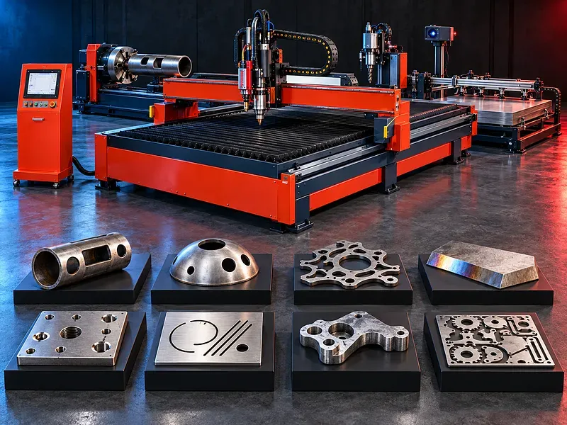
Gantry plasma cutting concept
The gantry beam spans the working area and carries the torch carriage and any compatible optional stations. Longitudinal drives move the bridge while transverse motion positions the cutting station across the plate.
Machine rigidity, guideway installation, drive synchronization, motion control, table condition, torch height control, plasma process, and nesting program all affect the cutting result.
Bridge guideways and dual side drive
Large gantries may be driven from both sides to keep the bridge square to the guideways during acceleration and cutting. Other layouts may use a different verified drive arrangement.
Rail straightness, parallelism, level, rack or drive condition, servo tuning, encoder feedback, bridge stiffness, foundation, and thermal environment require controlled installation and maintenance.
Cutting table and work area
The cutting table supports plate above a zone that receives sparks, molten material, fumes, and slag. Table designs may use dry extraction zones, a water pan, replaceable slats, or another verified arrangement.
Working width and length, plate size and weight, slat spacing, loading method, part retrieval, remnant handling, simultaneous zones, pendulum operation, and expansion plans should be reviewed from the production flow.
Plasma power source and process gas
The plasma power source generates the controlled arc used to melt and eject material along the programmed path. Gas and electrical systems must match the material, thickness, torch, current range, cut quality, and duty cycle.
Gas type, purity, pressure, flow, mixing, drying, filtration, regulators, hoses, grounding, current output, duty rating, consumables, cooling, and interface require approved system documentation.
Torch height control and arc sensing
Automatic torch height control may use initial height sensing, arc voltage feedback, collision protection, retract moves, and programmed delays to maintain a suitable distance during piercing and cutting.
Plate movement, slag, coatings, moisture, grounding, corner slowdown, small features, bevel motion, consumable wear, and process settings can affect height control and cut quality.
CNC control display and programming
The CNC and operator display manage programs, axis motion, job setup, part coordinates, cutting data, torch control, diagnostics, alarms, and optional stations according to the system configuration.
Programs should use verified cutting data, lead paths, piercing positions, safe moves, kerf compensation, corner strategy, cut sequence, remnant management, simulation, and controlled first part approval.
Nesting and material utilization
Nesting software arranges parts on the plate and may support common lines, bridges, remnants, grain direction, part identification, production reporting, and integration with other systems when provided.
Material utilization depends on part mix, kerf, spacing, lead paths, thermal movement, small part retention, cut sequence, skeleton stability, quality zones, bevel allowance, and handling requirements.
Fume extraction and filtration
Plasma cutting produces fumes, fine particles, gases, sparks, and hot slag. A dry table may use zoned extraction, while another system may use water based capture or local extraction according to the verified design.
Airflow, capture velocity, ducting, table zoning, filter media, spark control, fire protection, fan capacity, noise, monitoring, maintenance, discharge, and processed materials must be considered together.
Conductive materials and applications
Plasma cutting is generally used on electrically conductive materials such as suitable carbon steels, stainless steels, aluminum, and other compatible metals. Each grade, coating, surface condition, thickness, and quality requirement needs review.
Potential applications include plates, brackets, structural parts, machinery components, tanks, frames, construction components, transport parts, agricultural equipment, and fabricated metal products.
Cutting capacity and thickness range
Capacity should be defined separately for recommended quality cutting, maximum production cutting, edge start, piercing, bevel cutting, marking, and any secondary operation. A single maximum thickness does not describe all usable results.
Material grade, current, gases, torch, consumables, piercing method, speed, duty cycle, edge quality, taper, dross, hole requirement, and downstream work determine practical capacity.
Cut quality heat effects and post processing
Acceptance may cover dimensions, kerf, taper, angularity, dross, edge roughness, heat affected zone, top edge rounding, bevel, hole quality, piercing condition, surface contamination, and downstream fit.
Plasma can reduce or increase secondary work depending on material, thickness, process settings, consumables, motion quality, extraction, acceptance criteria, and later welding or machining. Nearly post processing free results should not be assumed.
2D cutting and bevel cutting
Standard 2D cutting uses a vertical torch path for profiles and internal features. Bevel cutting uses a controlled tilting head or other verified arrangement for weld preparation, chamfers, and selected angled edges.
Bevel type, angle, land, root face, thickness, head range, tool center compensation, collision envelope, software, calibration, quality, and additional cutting allowance require exact verification.
Drilling tapping and countersinking
A combined system may carry a drilling or machining station for selected holes, tapping, countersinking, spot facing, or marking when the bridge, table, spindle, workholding, software, and guarding support these operations.
Spindle taper, speed, torque, feed, tool changer, lubrication, chip control, plate support, clamping, hole range, thread range, depth, accuracy, and process sequence require separate technical confirmation.
Marking scanning and part identification
Optional marking may use plasma, scribing, punching, ink, laser, or another verified method. Scanning may support plate alignment, contour detection, remnant recognition, or quality functions according to the system.
Mark permanence, readability, depth, heat effect, code format, scanner accuracy, calibration, surface condition, software, traceability, and data integration should match the production requirement.
Pipe profile and dome processing
Pipe, profile, and dome processing require specialized axes, fixtures, supports, rotators, head access, scanning, software, and cutting strategies beyond a basic flat plate gantry system.
Part diameter, length, weight, section shape, straightness, rotation, support spacing, chuck or fixture, seam position, bevel, collision risk, loading, and unloading require application specific engineering.
Multiple torches gantries and production zones
Some systems may use multiple torches, more than one gantry, or separated loading and cutting zones to increase output or support different processes when the table, extraction, control, gas, power, and safety systems are engineered for the arrangement.
Part mix, nesting, torch spacing, cut sequence, power demand, gas flow, fume load, heat input, bridge interference, maintenance access, and operator control determine whether parallel production is useful.
Comparison with other cutting methods
Plasma may offer favorable cutting speed and cost for many conductive metal applications, particularly within suitable thickness and quality ranges. The result should be compared with laser, waterjet, oxyfuel, saw cutting, or machining for the actual part.
Laser may offer different precision and small feature performance. Waterjet limits thermal effects and cuts a broader material range. Oxyfuel can suit thick carbon steel. No process is universally best or the only solution for a material.
Consumables and operating cost
Consumables may include electrodes, nozzles, shields, retaining caps, swirl rings, cooling parts, gas filters, torch leads, table slats, lubricants, extraction filters, and marking or drilling tools when installed.
Cost per part depends on current, gases, cutting time, piercing, consumable life, nesting, material utilization, extraction, energy, labor, maintenance, dross removal, secondary work, downtime, and waste handling.
How to choose the correct machine
Provide CAD files and drawings, material grades, plate sizes and weights, thickness range, feature details, bevels, holes, threads, marks, tolerances, edge quality, quantities, batch sizes, target output, and downstream operations.
Selection should review working area, rail length, gantry count, torch count, plasma source, current range, gases, height control, bevel head, drilling station, marking, scanning, pipe options, nesting, extraction, filtration, loading, unloading, automation, guarding, utilities, floor space, and future work.
Technical information to verify
Approved technical documents must confirm the machine structure, working width and length, axis travels, rail and drive arrangement, rapid and feed rates, positioning accuracy, repeatability, table type, allowable plate load, torch count, supported stations, and control system.
They must also confirm plasma source, current range, duty rating, gas requirements, verified cut and pierce capacities by material and quality level, torch height control, bevel functions, drilling and marking data, extraction airflow, filters, software, electrical supply, air, cooling, dimensions, weight, foundation, guarding, included equipment, and options.
Safety and operating risks
The risk assessment should cover electric arc, ultraviolet and infrared radiation, hot metal, sparks, fire, fumes, gases, moving gantries, torch motion, crushing and collision zones, high voltage, compressed gases, coolant, noise, heavy plates, suspended loads, and maintenance isolation.
Required controls may include verified guarding, screens, interlocks where provided, emergency stops, extraction, fire detection and response, grounding, gas monitoring where required, lifting plans, exclusion zones, suitable personal protection, training, and documented lockout procedures.
Installation maintenance and lifecycle support
Site planning should cover foundation and rail engineering, floor loading, leveling, electrical supply, grounding, compressed gases and air, cooling, extraction ducting, filtration, fire precautions, cranes, plate flow, loading and unloading, scrap handling, maintenance clearance, and operator and programmer training.
Preventive maintenance should follow approved documents for rails, racks or drives, gearboxes, servos, bridge alignment, torch carriage, height control, plasma source, torch, leads, gases, cooling, table, extraction, filters, CNC, drilling or marking stations, guards, backups, and calibration.
Environmental and waste controls
Fumes, filter dust, slag, spent consumables, scrap skeletons, coolant, water table residues, and cleaning waste must be characterized and handled according to the processed materials and local requirements.
Coatings, stainless steel, alloying elements, and hazardous materials can change exposure and waste controls. Extraction performance, filter disposal, fire risk, noise, water treatment, housekeeping, and spill prevention should be planned before production.
Limitations and alternative processes
Plasma cutting is limited to electrically conductive materials and can produce thermal effects, dross, taper, noise, fumes, and consumable wear. Small features, tight tolerances, reflective surfaces, thick sections, or finish requirements may favor another process.
Depending on the part, alternatives may include laser, waterjet, oxyfuel, saw cutting, milling, punching, shearing, wire electrical discharge machining, robotic plasma, or another dedicated process.
Technical review and next step
Send CAD files and drawings, material grades, plate dimensions and weight, thickness range, cut features, bevels, holes, threads, marking needs, tolerances, edge criteria, quantities, target output, utilities, floor plan, extraction route, loading method, and waste constraints for technical review.
The technical review will identify the suitable gantry and table, plasma process, gases, torch and height control, optional stations, nesting, extraction, filtration, quality plan, safety controls, installation needs, and any sample cutting requirement.
Questions we are asked
What is a CNC gantry plasma cutting machine?
It is a CNC thermal cutting system that moves a plasma torch and optional stations across a guided bridge over a cutting table for suitable conductive metal work.
Which materials can plasma cut?
Plasma is generally used for suitable electrically conductive metals. The exact grade coating thickness and required quality must be reviewed with the plasma process.
Does every gantry system drill bevel scan and cut pipe?
No. These functions require specific heads stations axes software workholding and safety systems and must be verified for the selected configuration.
Does plasma always eliminate post processing?
No. Dross taper heat effects hole quality and edge requirements may still require cleaning machining grinding or another downstream operation.
How is plasma compared with laser waterjet and oxyfuel?
The correct choice depends on material thickness feature size edge quality heat tolerance speed cost secondary work and production volume. No method is universally best.
What information is required for selection?
Provide CAD files material grades plate sizes weights thicknesses cut and bevel details holes threads marking tolerances edge criteria quantities target output utilities floor plan extraction route and loading method.
Tell us the part you need to make
An engineer reads every request. Usually the same working day.
Related
- CNC Hydraulic Press Brake CNC-controlled hydraulic press brakes for bending sheet metal components according to defined angles, dimensions and production requirements.
- CNC TUBE BENDING MACHINE CNC tube bending machines control the bending sequence to produce defined tube and pipe geometries. Selection depends on the material, section, diameter, wall thickness, bend radius, part geometry, accuracy, and production volume.
- Dished Head Flanging Machines A dished head flanging machine forms the knuckle and straight flange of supported vessel heads after the blank has been prepared or dished. The correct configuration depends on the head diameter, thickness, material, profile, central opening, forming temperature, tooling, handling, tolerance, and required output.