

Hydraulic Sheet Metal Bending
CNC Hydraulic Press Brake
CNC-controlled hydraulic press brakes for bending sheet metal components according to defined angles, dimensions and production requirements.
A CNC Hydraulic Press Brake uses a hydraulic drive system to move the ram and bend sheet metal between a matched upper tool and lower die. The CNC system coordinates the bending sequence, ram position and backgauge movements according to the machine configuration.
Selecting the right machine requires the material grade, thickness range, maximum bend length, part drawings, bend angles, flange dimensions, tolerances and production target. Explore our sheet metal machines or send your drawings for technical selection.
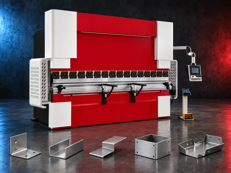
Typical Applications:
- Electrical cabinets, enclosures and control panels
- Brackets, covers, trays, doors and frames
- Machine guards and industrial housings
- HVAC and ductwork components
- Stainless-steel fabrication
- Architectural metal components
- General sheet metal fabrication
- Repeat bending of suitable production parts
How Does a CNC Hydraulic Press Brake Work?:
The hydraulic system generates and controls the force required to move the ram. The sheet is positioned against a CNC-controlled backgauge before the upper tool presses it into the lower die to produce the programmed bend.
Depending on the model, synchronized hydraulic cylinders and position-measuring systems may control the ram movement. The exact hydraulic architecture, axes and control functions must be verified from the official model documentation.
Actual accuracy and repeatability depend on the machine, tooling, material consistency, bend length, setup, operator practice and inspection method.
How to Select the Right Machine:
- 1. Define the material type, grade and tensile strength.
- 2. Specify the minimum and maximum sheet thickness.
- 3. Confirm the maximum bend length and overall part dimensions.
- 4. Review every bend angle, internal radius and minimum flange.
- 5. Calculate the required force using the actual material, thickness, bend length, die opening and bending method.
- 6. Define the required positioning accuracy and repeatability.
- 7. Select the required backgauge axes and CNC functions.
- 8. Confirm the tooling, clamping and crowning requirements.
- 9. Review hydraulic cooling, oil and maintenance requirements.
- 10. Confirm safety systems, material handling, electrical supply, floor loading and installation space.
Technical Data to Verify:
- Nominal bending force
- Maximum bending length
- Distance between side frames
- Throat depth
- Ram stroke and open height
- Table and ram dimensions
- Hydraulic cylinder and synchronization system
- CNC-controlled axis configuration
- Backgauge travel and positioning range
- Positioning accuracy and repeatability
- Approach, bending and return speeds
- Tooling interface and clamping system
- Crowning or deflection-compensation system
- Angle-measurement or correction options
- Hydraulic tank capacity and specified oil type
- Hydraulic cooling or temperature-control requirements
- Safety and operator-protection system
- Main motor power and electrical supply
- Machine dimensions, weight and foundation requirements
All technical values must be taken from the latest official documentation for the selected brand and model.
Standard and Optional Equipment:
Depending on the selected model, equipment may include:
- CNC control system
- Synchronized hydraulic ram control
- Multi-axis backgauge
- Upper and lower bending tools
- Manual, hydraulic or automatic tool clamping
- Mechanical or CNC-controlled crowning
- Front material-support arms
- Sheet followers or lifting supports
- Oil cooler or hydraulic temperature-control system
- Laser or camera-based angle-measurement system
- Light curtains or laser-based safety protection•
- Side and rear safety guards
- Offline programming software
- Automatic tool-changing system
- Robotic loading and unloading integration
Standard equipment, optional equipment and included tooling must be confirmed in the approved quotation.
Application Limits:
Nominal force alone does not confirm machine suitability. Material strength, thickness, bend length, die opening, tooling capacity, flange dimensions and bend geometry must be reviewed together.
Hydraulic oil condition and temperature can affect operation and maintenance. The oil specification, cooling requirements and service intervals must follow the official manufacturer instructions.
A CNC Hydraulic Press Brake is not a replacement for sheet cutting, punching, stamping or plate rolling machines. Complex parts, small flanges and special materials may require dedicated tooling, additional axes or an alternative forming process.
Installation and Support:
- Application and part-drawing review
- Site, floor-loading and electrical assessment
- Hydraulic oil and operating-environment review
- Machine unloading and positioning requirements
- Installation, levelling and commissioning
- Hydraulic and CNC operating checks
- CNC control and operator training
- Bending-tool selection and application guidance
- Preventive-maintenance planning
- Spare-parts, hydraulic components and consumables support
- Warranty according to the approved quotation
The exact installation, training, service, tooling and warranty scope must be confirmed for the selected model and approved commercial offer.
Request a Technical Recommendation:
Send the part drawings, material grade, thickness range, maximum bend length, bend details, tolerances and production volume to determine the appropriate bending force, machine length, CNC axes, tooling and hydraulic configuration.
Questions we are asked
What is a CNC Hydraulic Press Brake?:
It is a programmable sheet metal forming machine that uses hydraulic power to move the ram and bend workpieces between an upper tool and a lower die.
What information is required to select the machine?:
Provide the part drawings, material grade, thickness range, maximum bend length, bend angles, internal radii, flange dimensions, tolerances and production volume.
How is the required bending force calculated?:
Required force depends on material strength, thickness, bend length, die opening and bending method. It must be calculated for the actual application.
Which CNC axes are required?:
The suitable axis configuration depends on part geometry, bending sequence, positioning requirements, accuracy and production volume.
Does the machine include bending tools?:
Tool type, profile, size, segmentation, load capacity and quantity must be confirmed in the approved technical and commercial offer.
What hydraulic maintenance is required?:
The approved oil type, filtration, temperature range, inspection points and maintenance intervals must follow the official manufacturer manual.
Are installation and operator training included?:
Installation, commissioning, training, tooling, warranty and service scope are defined in the approved quotation for the selected model.
Tell us the part you need to make
An engineer reads every request. Usually the same working day.
Related
- CNC TUBE BENDING MACHINE CNC tube bending machines control the bending sequence to produce defined tube and pipe geometries. Selection depends on the material, section, diameter, wall thickness, bend radius, part geometry, accuracy, and production volume.
- CNC Gantry Plasma Cutting Machines A CNC gantry plasma cutting machine moves one or more cutting stations across a guided bridge to process suitable electrically conductive plate and supported profiles. The correct configuration depends on the material, thickness, plate size, part geometry, edge quality, bevels, secondary operations, extraction, automation, and required output.
- Dished Head Flanging Machines A dished head flanging machine forms the knuckle and straight flange of supported vessel heads after the blank has been prepared or dished. The correct configuration depends on the head diameter, thickness, material, profile, central opening, forming temperature, tooling, handling, tolerance, and required output.