

STRUCTURAL STEEL PROCESSING LINES
Three Spindle CNC Beam Drill Lines
A three spindle CNC beam drill line processes multiple faces of compatible structural steel profiles in a controlled production flow. The correct configuration depends on profile type and size, material, hole pattern, machining operations, tolerances, tools, handling, software, output, and downstream fabrication.
The line typically positions a beam or structural profile through a machining zone where three spindle units can approach different faces. Depending on the verified configuration, the line may perform drilling, marking, tapping, countersinking, and milling with automatic tool management and programmed positioning. Feeding arms, clamps, measurement systems, transfer tables, saw integration, marking devices, software, and automatic handling can form part of a connected production line. Their actual scope, capacity, sequence, and interfaces require confirmation from approved technical documents.
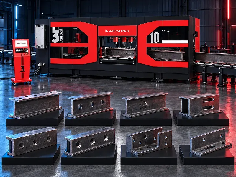
What a three spindle beam drill line does
The line machines structural steel profiles by coordinating material positioning with spindle movement and programmed tool paths. Three spindle units can address selected profile faces according to the machine arrangement and approved program.
The exact number of controlled axes, simultaneous operations, working envelope, profile range, and achievable cycle depend on the selected configuration and should not be inferred from the category name alone.
Three spindle architecture
A typical arrangement uses spindle units positioned to process the web and flanges of a compatible profile. Independent spindle movement can reduce repositioning and may allow different operations to be coordinated on separate faces.
Spindle orientation, travel, sub axis movement, collision zones, tool reach, simultaneous motion, and supported profile geometry require verification from the approved machine layout.
Material positioning and auxiliary travel
The feed system moves the profile to the programmed reference while an auxiliary travel or spindle axis may extend machining coverage without moving the full workpiece. This can support closely spaced features or operations along a defined length.
Auxiliary travel, positioning accuracy, reference method, compensation, measurement feedback, and the conditions under which the workpiece remains stationary require page specific technical confirmation.
Drilling
Drilling creates holes for structural connections, fabrication, assembly, or subsequent machining. Tool selection should match hole diameter, depth, material grade, spindle interface, coolant method, and required quality.
Hole range, spindle speed, feed, power, torque, drill type, coolant delivery, breakthrough control, chip evacuation, and achievable tolerance require verification for the exact machine and tool.
Carbide drilling
Carbide tools may support higher cutting parameters and longer tool life when the spindle, toolholder, rigidity, coolant, material, and process are suitable. Tool data should come from the approved tool supplier and machine limits.
Carbide drilling performance varies with material condition, hole depth, interruptions, scale, clamping, coolant, and chip control. Speed and productivity claims require validated cutting trials.
Marking and identification
A marking unit can identify part references, assembly locations, orientation, or fabrication information on supported surfaces. The method may use a machining tool or dedicated marking device according to the configuration.
Number of marked faces, character size, depth, legibility after painting or blasting, data source, cycle time, and traceability require verification. Marking should follow the approved production and quality plan.
Milling
Milling can create slots, notches, flat features, enlarged openings, or supported contours when the spindle, tool, travels, and workholding are suitable. Tool path and cutting parameters should be validated against the drawing.
Milling envelope, interpolation, depth, surface finish, dimensional tolerance, tool diameter, chip evacuation, and cycle time require technical confirmation. The line should not be presented as a general machining center.
Tapping
Tapping creates internal threads in prepared holes. The process requires synchronization of spindle rotation and feed, suitable hole size, tool selection, lubrication or coolant, and controlled reversal.
Thread standards, size range, depth, material limits, rigid tapping capability, tool monitoring, and recovery from a broken tap require verification before the operation is offered.
Countersinking
Countersinking forms a conical seat at the mouth of a drilled hole for a compatible fastener or finishing requirement. The tool, angle, depth, diameter, and surface quality should match the approved drawing.
Countersink range, angle options, depth control, repeatability, tool type, inspection method, and compatibility with the required fastener need confirmation.
Automatic tool changing
An automatic tool changer can store multiple tools for each spindle and call the programmed tool without manual exchange during the cycle. This can reduce handling and support multi operation programs when correctly configured.
Tool stations, magazine arrangement, tool interface, maximum tool dimensions, tool identification, change time, life tracking, broken tool detection, and safe recovery require approved documentation.
Material clamping
Hydraulic or mechanical clamps hold and reference the profile during positioning and machining. Adjustable jaws may accommodate a range of profiles when the clamping surfaces and travel are suitable.
Clamping points, force, jaw travel, profile contact, distortion risk, minimum grip, reference datum, sensor confirmation, and safe release sequence require verification.
Automatic material measurement
Independent measurement devices may detect profile length, width, height, flange position, or local variation before machining. The control can use measured data to establish references or apply permitted compensation.
Measured dimensions, sensor type, reference method, measurement points, accuracy, calibration, compensation limits, error handling, and record storage require technical approval.
Feeding arm and profile movement
A feeding arm or gripper can locate and advance the profile through the line. Positive engagement can support controlled positioning when the profile, clamping, rack, drive, and measurement system are correctly matched.
Feed length, speed, force, positioning method, minimum remnant, profile range, collision protection, grip confirmation, and recovery after interruption must be verified.
Transfer tables and conveyors
Infeed and outfeed conveyors support the material before and after machining. Transfer tables can move profiles between parallel paths, machines, saws, or unloading positions when integrated into the layout.
Table length, roller spacing, load capacity, cross transfer stroke, speed, sensors, controls, safe zones, accumulation logic, and interfaces require an approved line layout.
Saw integration
A compatible band saw may be integrated with the drill line to cut profiles to length or form supported miters. The saw can receive production data and exchange material with the drilling system when the interfaces are approved.
Cutting range, angle range, blade data, saw capacity, measuring reference, sequence, remnant handling, chip control, guarding, and software exchange are integration dependent.
Marking an additional face
An additional marking arrangement may allow identification on a surface that is not directly reached by the main spindle layout. This can support assembly orientation and part traceability.
Supported face, access, marking method, depth, character range, cycle impact, collision protection, and visibility after coating or blasting require confirmation.
Programming and software
Programming may be performed from drawings, production lists, three dimensional models, or structural fabrication data when compatible import and post processing tools are available. Simulation can help review tool paths and collisions before production.
Controller type, software package, file formats, nesting or production planning functions, licenses, network requirements, post processor, backup, user access, updates, and cybersecurity responsibilities require written confirmation.
Typical production workflow
The workflow normally includes reviewing fabrication data, confirming material and profile, importing or creating the program, assigning tools, preparing stock, loading, measuring, clamping, positioning, machining each required operation, unloading, identifying the part, and inspecting the result.
Integrated cutting, marking, or transfer stages should be validated as one line. Trial parts and a first article inspection should be completed before releasing production batches.
Profiles and materials
Potential workpieces include supported beams, columns, channels, angles, hollow sections, flats, or fabricated profiles when the clamping, working envelope, spindle access, and process are suitable.
Material grade, yield strength, tensile strength, dimensions, straightness, twist, mill scale, welds, surface condition, and section variation influence machining. Exact profile and material limits require approval.
Quality and inspection
Inspection can include hole diameter, position, spacing, perpendicularity, thread quality, countersink diameter and depth, milled feature dimensions, marking legibility, part length, cut angle, and relationship between faces.
The drawing datum, tolerance, measurement equipment, sampling plan, first article process, calibration status, traceability, and nonconforming part procedure should be defined before production.
Applications
Potential applications include structural steel frames, buildings, bridges, industrial plants, material handling systems, energy structures, machinery frames, transport equipment, ship structures, and fabricated steel assemblies.
Industry suitability depends on the actual profile, connection design, fabrication code, quality plan, production volume, and downstream welding or assembly requirements.
How to choose the correct line
Provide profile types and size ranges, material grades, maximum stock length and mass, hole diameters and depths, operations, tolerances, face access, tool requirements, batch mix, annual tonnage, cycle targets, and downstream processes.
Also provide layout space, crane and loading data, infeed and outfeed direction, saw requirement, transfer logic, software formats, electrical supply, compressed air, coolant, extraction, foundation, staffing, shift pattern, safety rules, and inspection method.
Technical information to verify
Approved documents must confirm profile capacity, stock length and weight, spindle count, axes, travels, spindle power, torque and speed, hole range, tool interfaces, tool stations, feed speed, positioning accuracy, operations, clamps, measuring systems, conveyors, saw interfaces, dimensions, weight, utilities, and foundation.
Control and software scope, licenses, integration responsibilities, safety system, extraction, coolant, chip collection, network requirements, training, spare parts, and acceptance test conditions also require confirmation.
Safety and operating risks
Risks include rotating tools, moving spindles, clamps, conveyors, transfer tables, long profiles, suspended loads, sharp edges, swarf, coolant, tool breakage, unexpected automatic movement, electrical energy, hydraulic pressure, and compressed air.
The line requires approved guarding, fenced zones, interlocked access, emergency stops, safe loading areas, presence sensing where specified, chip control, lockout procedures, lifting plans, operating instructions, personal protective equipment, training, and a documented risk assessment.
Installation and commissioning
Site planning should cover layout, access, unloading, foundations, anchoring, leveling, electrical supply, air, coolant, extraction, network connection, lighting, guarding, conveyors, saw interface, cranes, material flow, chip handling, and maintenance access.
Commissioning should include geometry, alignment, spindle tests, tool changing, clamps, measurement calibration, conveyors, transfer tables, saw communication, safety validation, software import, trial profiles, first article inspection, operator training, maintenance training, and document handover.
Maintenance and lifecycle support
Preventive maintenance should follow approved schedules for spindles, toolholders, changers, axes, guides, racks, drives, clamps, measuring sensors, conveyors, transfer tables, hydraulics, lubrication, coolant, chip systems, guards, interlocks, and electrical controls.
Recommended tools, consumables, filters, lubricants, spare parts, calibration devices, backups, software support, remote access rules, training, service intervals, and technical documents should be agreed for the selected line.
Limitations and publication status
The supplied text refers to a specific commercial configuration, but the requested page omits company and model identity. Therefore numerical travel, hole range, tool stations, speed, power, axes, saw angles, marking faces, capacity, accuracy, and productivity are not presented as generic facts.
The page requires an approved page specific datasheet, confirmed option list, technical review, approved media, staging review, and final content approval before publication.
Questions we are asked
What is a three spindle beam drill line?
It is a CNC production line that positions structural steel profiles while three spindle units machine selected faces according to the programmed operations.
Which operations can the line perform?
Depending on the verified configuration it may perform drilling marking milling tapping countersinking measurement and integrated cutting. Each operation and range requires confirmation.
Can all three spindles work at the same time?
Independent or simultaneous spindle operation may be available within defined travel tool and collision limits. The exact sequence depends on the machine layout and program.
Can the line connect to a band saw?
Saw integration may be available when mechanical material handling electrical controls safety logic measuring references and software interfaces are approved together.
What information is needed for selection?
Provide profile ranges materials stock length and weight hole patterns operations tolerances tools annual tonnage software formats saw and transfer requirements utilities layout staffing shifts and inspection method.
Tell us the part you need to make
An engineer reads every request. Usually the same working day.
Related
- CNC Hydraulic Press Brake CNC-controlled hydraulic press brakes for bending sheet metal components according to defined angles, dimensions and production requirements.
- CNC TUBE BENDING MACHINE CNC tube bending machines control the bending sequence to produce defined tube and pipe geometries. Selection depends on the material, section, diameter, wall thickness, bend radius, part geometry, accuracy, and production volume.
- CNC Gantry Plasma Cutting Machines A CNC gantry plasma cutting machine moves one or more cutting stations across a guided bridge to process suitable electrically conductive plate and supported profiles. The correct configuration depends on the material, thickness, plate size, part geometry, edge quality, bevels, secondary operations, extraction, automation, and required output.