

AUTOMATED SHEET METAL BENDING
Panel Bending Machines
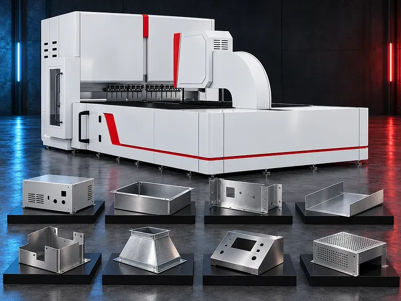
Panel bending machines clamp, position, and form compatible sheet metal into panels, profiles, and components with multiple edges and flanges. Correct selection depends on the material, blank dimensions, bend length, flange geometry, angle, radius, sequence, tolerance, batch mix, handling method, and required output.
During a panel bending cycle, the blank is located and clamped while bending blades move around the sheet edge to form an upward or downward flange when supported by the machine configuration. Automatic handling or repositioning may rotate and advance the part between bends. Panel bender and panel folder are commonly used terms for this equipment category, but machine designs vary. Material capacity, maximum bend length, flange limits, tooling, positioning method, angle control, accuracy, cycle time, automation, and safety systems must be confirmed for the exact machine.
How panel bending works
The sheet blank is positioned against a reference system and held by a clamping tool. A bending blade or blade group moves relative to the clamped edge and forms the flange through a controlled path.
The machine may reposition the blank for additional sides and bends. Clamping, blade trajectory, material support, bend sequence, springback compensation, and programmed dimensions influence the finished geometry.
Clamping and blank holder system
The blank holder secures the sheet near the bend line and provides a reference for the bending action. Its shape, segmentation, pressure, height, clearance, and contact condition must match the part and process.
Blank holder length, segmented tools, automatic tool setup, clamping force, surface marking risk, minimum clearance, tool change method, and compatibility with boxes or return flanges require exact machine confirmation.
Upper and lower bending blades
Depending on the design, bending blades may form flanges upward, downward, or in supported combinations. The blade follows a controlled movement while the sheet remains clamped or is repositioned for the next operation.
Blade material, geometry, length, edge radius, clearance, travel, force, speed, alignment, wear limits, lubrication, and supported bending directions must be verified for the selected machine and part family.
Automatic positioning and manipulation
A manipulator, gripper, suction system, back gauge, reference pins, or another positioning arrangement may locate, rotate, and advance the blank between bends according to the program.
Maximum and minimum blank dimensions, part mass, gripping area, holes and cutouts, surface condition, rotation clearance, positioning range, accuracy, collision zones, and unsupported shapes require review.
Bend length and material capacity
Capacity depends on material grade, yield and tensile strength, thickness, bend length, flange height, angle, radius, tooling, blank size, sequence, and machine structure. Thickness alone does not define suitability.
Carbon steel, stainless steel, aluminum, coated sheet, and other materials should only be listed when the exact capacity and surface requirements have been verified for the selected machine and condition.
Flange height and part geometry
The drawing should define every flange height, bend direction, angle, radius, hem, offset, return, corner relief, opening, cutout, and relationship to previous bends. The complete bend sequence should be checked for tool and part clearance.
Minimum and maximum flange height, return flange capability, box depth, internal clearance, diagonal limits, collision risk, and access to narrow or deep features vary by design and require verification.
Bend angle radius and springback
The final angle and radius depend on material grade, thickness, rolling direction, temper, coating, tool geometry, programmed movement, clamping, springback, and measurement method.
Angle correction and springback compensation may use approved material data, sensors, adaptive control, or trial results according to the machine configuration. Accuracy should be validated on the actual part and material.
Multiple bends and sequence planning
Panel parts can require several bends on one or more sides. The sequence must preserve access for clamping and tools while controlling collision, part support, accumulated tolerance, springback, and the effect of earlier bends.
A suitable program should define reference edges, blank orientation, bend order, directions, dimensions, angles, speed, repositioning, handling, checks, and corrective values. Simulation does not replace first part verification.
Tooling setup and changeover
Panel bending systems can use full length, segmented, manually arranged, or automatically configured tooling according to the design. Tooling should support the required flange while clearing corners, returns, openings, and formed features.
Tool inventory, lengths, segments, radii, holder interfaces, setup method, automatic arrangement, storage, identification, wear, cleaning, maintenance, and replacement scope require confirmation.
CNC programming and control
The CNC may manage dimensions, angles, blade paths, clamping, manipulator movement, part rotation, tool setup, speeds, sequences, corrections, alarms, and production data according to the installed system.
Controller type, axes, program capacity, drawing import, offline programming, simulation, language, user permissions, backups, network connection, diagnostics, reporting, and optional functions require written approval.
Material variation and compensation
Sheet thickness, strength, hardness, rolling direction, coating, flatness, residual stress, cut quality, blank dimensions, and lot variation can change bend behavior and final geometry.
Compensation should be based on approved settings, measurement, controlled trials, or supported adaptive functions. Automatic correction cannot guarantee acceptable parts when incoming material or blanks are outside the approved condition.
Part support and surface protection
Large or flexible blanks need controlled support during positioning and bending. Brushes, rollers, tables, followers, suction devices, or dedicated supports may reduce sagging, uncontrolled movement, and surface damage when compatible with the part.
Support area, load, height, movement, contact material, cleanliness, marking risk, coating sensitivity, protective film, part overhang, and operator access should be reviewed for the application.
Production workflow
The process normally begins with the approved drawing, blank development, material specification, tooling check, bend sequence, program preparation, sheet identification, machine setup, and safety validation.
The blank is loaded, referenced, clamped, bent, repositioned, and measured. The first part should be inspected and approved before batch release, with corrections, traceability, and nonconforming part handling controlled through the quality plan.
Quality and inspection
Inspection may cover overall dimensions, flange heights, angles, radii, straightness, flatness, diagonals, squareness, hole and cutout positions, hems, offsets, corner condition, surface marks, and fit with mating parts.
The inspection plan should define datum, tolerances, tools, fixtures, sampling, calibration, first part approval, process monitoring, correction limits, traceability, and final acceptance.
Productivity and repeatability
Automatic positioning and programmed bending can reduce some manual handling and repeated setup when the part geometry, blank, tooling, machine capacity, and production mix are suitable.
Cycle time, output, repeatability, labor reduction, and consistency should not be guaranteed from the category alone. They depend on loading, unloading, bend count, repositioning, tool setup, material variation, inspection, maintenance, and operator practice.
Industrial applications
Potential applications include cabinets, electrical enclosures, shelving, architectural panels, elevator components, steel furniture, doors, clean room products, appliance panels, industrial covers, trays, frames, and machinery components.
Application suitability depends on material, blank size, flange geometry, bend sequence, surface finish, tolerance, batch mix, joining method, handling, downstream operations, and the applicable product standard.
Panel bender and press brake selection
A panel bender can suit parts dominated by panel edges and repeated flanges when its tooling and manipulator can handle the blank and sequence. It may reduce manual repositioning for compatible geometries.
A press brake may be more suitable for other part sizes, heavy materials, long profiles, deep tools, special forms, low volume flexible work, or geometries outside the panel bender envelope. Selection should compare actual part families rather than machine labels.
How to choose the correct machine
Provide part drawings, flat patterns, material grades and condition, minimum and maximum thickness, blank dimensions and mass, bend lengths, flange heights, angles, radii, directions, hems, returns, cutouts, tolerances, surface requirements, quantities, and target output.
Also define tooling needs, loading and unloading, automation, part support, inspection, shift pattern, utilities, floor space, safety rules, downstream joining, future part range, data integration, and acceptance trial requirements.
Technical information to verify
Approved documents must confirm material capacities, maximum bend length, minimum and maximum flange limits, supported angles and radii, blank dimensions and mass, manipulator range, positioning accuracy conditions, bending force, speed, cycles, tools, axes, and controls.
Machine dimensions, weight, floor loading, foundation, electrical supply, air, lubrication, cooling, noise test basis, guarding, safety functions, loading systems, software, standard equipment, options, environmental limits, documentation, training, and acceptance method also require confirmation.
Safety and operating risks
Risks include clamping and bending tool crushing, manipulator movement, automatic sheet rotation, sharp edges, unstable blanks, dropped parts, unexpected cycle start, suction loss, tool change, electrical hazards, compressed air, and maintenance work.
The safety concept should include approved guards, interlocked access, scanners or light curtains where suitable, emergency stops, safe setup mode, controlled loading zones, part supports, tool handling, lockout procedures, inspection, training, supervision, and a documented risk assessment.
Installation and commissioning
Site preparation should cover delivery access, unloading, floor capacity, foundation, anchoring, leveling, electrical isolation, compressed air where required, lighting, working clearances, guarding, material routes, loading equipment, part storage, and maintenance access.
Commissioning should include geometry, level, tool alignment, clamping, blade paths, manipulator calibration, control and software tests, utility checks, safety validation, program trials, sample bending, inspection, operator training, maintenance training, and document handover.
Maintenance and lifecycle support
Preventive maintenance should follow approved schedules for bending blades, blank holder tools, guides, drives, gears, bearings, lubrication, hydraulic or pneumatic components, grippers, suction devices, sensors, controls, tables, guards, interlocks, and emergency systems.
Recommended tools, wear parts, seals, filters, lubricants, sensors, suction elements, calibration devices, software backups, service tools, technical support, training, inspection records, and documentation should be agreed for the selected machine.
Limitations and publishing status
The supplied description does not prove precise or repeatable bending, tight tolerances, shorter cycle time, stable output, reduced operator variation, or suitability for small batches and series production. These results depend on the exact machine, part, material, tooling, program, handling, and inspection.
The page needs an approved datasheet for the exact machine, verified part and material capacities, confirmed tooling and automation scope, approved images, technical review, staging review, and final content approval before publication.
Technical review and next step
Send part drawings and flat patterns, material details, blank dimensions, bend lengths and directions, flange heights, angles, radii, returns, cutouts, tolerances, quantities, target output, surface requirements, handling method, utilities, and site layout for technical review.
The review should compare the part family with approved machine data and identify the suitable panel bender configuration, tooling, program method, supports, automation, inspection, safety concept, acceptance trial, installation, training, maintenance, and spare parts scope.
Questions we are asked
What is a panel bending machine?
It is a sheet metal forming machine that clamps and positions a compatible blank while bending tools create programmed edges flanges and panel geometries.
Is a panel bender the same as a panel folder?
The terms are often used for the same equipment category but machine designs levels of automation tooling and supported part geometries can differ and should be verified.
Which parts suit panel bending?
Potential parts include compatible cabinets enclosures shelves panels doors trays frames and covers when their blank size flange geometry material bend sequence and tolerances fit the verified machine envelope.
Does automation guarantee bend accuracy?
No. Accuracy also depends on material variation blank quality tooling calibration programming support measurement maintenance and first part approval.
What information is needed for selection?
Provide part drawings flat patterns material thickness blank size bend lengths flange heights angles radii returns cutouts tolerances quantities target output handling needs utilities and site layout.
Tell us the part you need to make
An engineer reads every request. Usually the same working day.
Related
- CNC Hydraulic Press Brake CNC-controlled hydraulic press brakes for bending sheet metal components according to defined angles, dimensions and production requirements.
- CNC TUBE BENDING MACHINE CNC tube bending machines control the bending sequence to produce defined tube and pipe geometries. Selection depends on the material, section, diameter, wall thickness, bend radius, part geometry, accuracy, and production volume.
- CNC Gantry Plasma Cutting Machines A CNC gantry plasma cutting machine moves one or more cutting stations across a guided bridge to process suitable electrically conductive plate and supported profiles. The correct configuration depends on the material, thickness, plate size, part geometry, edge quality, bevels, secondary operations, extraction, automation, and required output.