

HYDRAULIC PLATE ROLLING MACHINES
Four Roll Plate Rolling Machines
A four roll plate rolling machine clamps compatible plate between upper and lower rolls while two side rolls control bending and prebending. Correct selection depends on material strength, plate thickness and width, target diameter, geometry, tolerance, supports, handling, and production requirements.
The four roll arrangement can grip the plate between the upper and lower rolls while a side roll rises to create curvature. The opposite side roll can support the plate and may assist with prebending or sequence control according to the verified machine design. The supplied description refers to hydraulic roll movement, independent adjustment, prebending, programmable control, feeding equipment, safety fencing, side supports, and vertical supports. These are configuration dependent functions and options that require confirmation from approved technical documents.
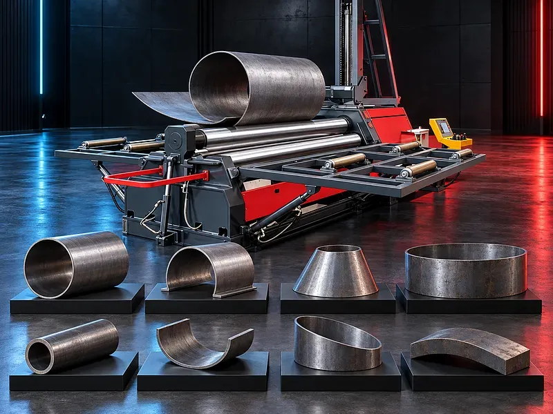
Four roll working principle
The upper and lower rolls clamp and drive the plate while the side rolls establish the bending position. Progressive movement and plate travel develop the required curvature.
The exact roll arrangement, driven rolls, movement sequence, clamping force, hydraulic circuit, and control logic vary by machine design and must be confirmed before publication.
Plate clamping and positioning
Clamping the plate between the upper and lower rolls can provide positive grip during alignment and rolling. Correct clamping helps control plate movement and may reduce repositioning when the process and machine are suitable.
Clamping pressure, roll traction, plate surface, material strength, alignment, and operator setup influence positioning. Claims of precise positioning or minimal manual adjustment require validation.
Prebending plate edges
Prebending reduces the straight section remaining at the leading and trailing plate edges. A side roll is positioned to bend the edge while the plate remains supported and clamped according to the approved sequence.
Prebending capacity may differ from rolling capacity. Remaining flat length depends on material strength, thickness, width, roll diameters, roll spacing, grip, support, and process settings.
Rolling cylinders and arcs
For cylindrical parts, the plate is aligned, clamped, prebent where required, and passed between the rolls while the side roll position is adjusted. Repeated passes may be required to reach the target diameter and compensate for springback.
Arc segments can be formed when the machine supports controlled start and stop positions. Diameter, radius, roundness, seam gap, edge alignment, and surface condition should be inspected against the approved drawing.
Cone forming
Cone forming requires the inner and outer plate edges to travel different paths. A verified cone rolling method, suitable roll movement, guides, cone device, plate development, and operator procedure may be required.
Cone angle, small diameter, large diameter, axial length, thickness, material strength, seam position, and surface limits must be reviewed. Cone capability should not be promised without approval for the required drawing.
Independent roll movement
Some machines allow separate positioning of the lower and side rolls to coordinate clamping, prebending, rolling, correction, and workpiece release. The available axes and movement method depend on the selected configuration.
Roll travel, positioning resolution, feedback, synchronization, compensation, stored positions, limits, and achieved repeatability require confirmation from the exact technical documentation.
Hydraulic power system
The hydraulic system may move the lower and side rolls, apply clamping force, operate the drop end, and control supports or other auxiliary functions. Stable pressure and controlled movement support consistent setup when the system is correctly maintained.
Maximum pressure, cylinder arrangement, valve control, oil specification, filtration, cooling, protection settings, leakage monitoring, and maintenance intervals require approved data.
Roll drive and plate movement
One or more rolls may be driven to feed the plate through the bending zone. Drive torque, traction, roll surface, speed, synchronization, plate condition, and support influence stable movement.
Motor power, hydraulic drive data, roll speed, torque limits, overload protection, braking, and recovery procedures must be verified for the selected machine.
Control system and programs
Controls may range from hydraulic operation with position indication to programmable systems that coordinate roll positions, pressure, stored steps, and automatic sequences. The exact interface and automation level are configuration dependent.
A programmable control does not guarantee accuracy. Material variation, preparation, alignment, roll deflection, springback, calibration, operator setup, and inspection affect the result.
Feeding system
A powered or passive feeding arrangement may support loading, alignment, or continuous material movement when included and integrated with the rolling process. It should match the plate size, mass, surface, and required sequence.
Feeding capacity, speed, alignment method, synchronization, support height, table geometry, controls, and safety integration require confirmation. The feeding system should not be assumed to be standard equipment.
Side and vertical supports
Side supports can help stabilize the plate or formed shell and reduce lateral movement. A vertical or overhead support can help carry a large diameter shell and reduce sagging during rolling.
Support capacity, travel, position, control, contact surfaces, supported diameter, lifting points, interference limits, and safe operating sequence must be selected from the actual workpiece and verified as included options.
Plate preparation and rolling workflow
The plate should be checked for dimensions, material identity, flatness, edge condition, weld preparation, surface defects, scale, and adequate allowance before rolling. Accurate alignment helps prevent helical rolling and uneven edges.
The workflow normally includes drawing review, capacity confirmation, plate preparation, loading, alignment, clamping, first edge prebending, body rolling, second edge prebending, diameter checking, springback compensation, correction, unloading, and final inspection.
A complete part in one pass should not be assumed. The number of passes depends on material, geometry, tolerance, machine capacity, process settings, and operator or program validation.
Materials and capacity
Capacity depends on material grade, yield strength, tensile strength, thickness, width, target diameter, rolling direction, temperature, prebending requirement, welds, and number of passes.
Carbon steel, stainless steel, aluminum, high strength steel, or other materials should only be listed after checking the exact machine capacity against approved material properties and part geometry.
Rolls and surface protection
Roll diameter, working length, material, hardness, surface finish, crown or compensation, bearing support, and alignment influence forming performance and plate condition.
Sensitive or polished material may require cleaned rolls, protective arrangements, controlled handling, or special surfaces. Claims of mark free rolling require trials on the actual material and finish.
Applications
Potential applications include cylindrical shells, tank sections, pressure vessel components, ducts, silos, pipes, cones, structural arcs, and fabricated metal products when the capacity and process are suitable.
Use in automotive, aerospace, construction, electronics, energy, machinery, ventilation, shipbuilding, or process equipment must be confirmed against the actual part, production standard, and required code.
Quality and inspection
Inspection can include diameter, radius, roundness, straightness, seam gap, edge alignment, cone dimensions, surface condition, local flattening, and dimensional consistency along the rolled length.
The measuring method, tolerance, sampling frequency, reference temperature, inspection tools, first part approval, and correction process should be defined before production.
How to choose the correct machine
Provide finished and blank drawings, material grade, yield strength, tensile strength, thickness range, maximum width, smallest diameter, prebending requirement, cone dimensions, tolerances, surface finish, weld details, batch size, and annual quantities.
Also provide production sequence, electrical supply, floor space, foundation data, crane capacity, loading route, feeding requirement, support requirement, operator access, safety rules, inspection method, and upstream and downstream processes.
Technical information to verify
Approved documents must confirm rolling capacity, prebending capacity, reference material strength, working length, minimum diameter, roll diameters, roll speed, drive power, hydraulic data, roll travel, controls, dimensions, weight, electrical supply, foundation, supports, feeding equipment, and options.
Capacity values must state their conditions. Maximum thickness at full width may differ from capacity at shorter width, and rolling capacity may differ from prebending or cone capacity.
Safety fence and operating risks
Risks include rotating rolls, nip and crushing points, moving plates, falling or springing material, unexpected roll movement, sharp edges, high hydraulic pressure, electrical hazards, and unsafe lifting.
A safety fence may isolate hazardous areas when it is correctly designed and interlocked. Fence layout, access gates, interlocks, reset points, emergency stops, safe distance, and maintenance access require a verified risk assessment.
The installation should include approved guards, exclusion zones, work supports, lifting plans, lockout procedures, personal protective equipment, trained operators, and documented safe operating procedures.
Installation and commissioning
Site preparation should cover access, unloading, floor loading, foundation, anchoring, leveling, electrical isolation, hydraulic service, lighting, working clearances, fencing, material flow, lifting equipment, and maintenance access.
Commissioning should include alignment, hydraulic and electrical checks, safety function tests, roll condition, calibration, trial rolling with approved material, support and feeding tests, operator training, sample inspection, and document handover.
Maintenance and lifecycle support
Preventive maintenance should follow approved schedules for hydraulic oil, filters, hoses, seals, cylinders, bearings, roll surfaces, guides, lubrication, alignment, drive components, sensors, controls, supports, feeding equipment, guards, and emergency systems.
Recommended spare parts, wear items, hydraulic consumables, service tools, calibration method, technical support, training scope, and document availability should be agreed for the selected machine.
Limitations and publication status
The supplied copy is generic and does not prove single pass forming, independent roll motion, heavy duty capacity, precision, speed, efficiency, stable pressure, repeatability, automation, reliability, or suitability for the listed industries.
The page requires an approved datasheet or manual for the exact machine, verified capacity calculations, technical review, approved images, staging review, and final content approval before publication.
Questions we are asked
What is a four roll plate rolling machine?
It is a plate forming machine that clamps plate between upper and lower rolls while two side rolls control bending and prebending according to the machine design.
What is the difference between rolling and prebending capacity?
Rolling capacity forms the main body while prebending capacity applies to the plate edges. Their rated thicknesses may differ and must be checked at the required width and material strength.
Can it finish a cylinder in one pass?
A single pass may be possible for some parts and validated programs, but the number of passes depends on material geometry tolerance springback capacity and process settings.
Are feeding and support systems included?
Feeding tables side supports vertical supports safety fences and programmable controls may be optional or configuration dependent. Their scope requires written confirmation.
What information is needed for selection?
Provide drawings material certificates yield strength thickness width diameters cone dimensions prebending requirement tolerances quantities utilities floor plan crane data support needs and inspection method.
Tell us the part you need to make
An engineer reads every request. Usually the same working day.
Related
- CNC Hydraulic Press Brake CNC-controlled hydraulic press brakes for bending sheet metal components according to defined angles, dimensions and production requirements.
- CNC TUBE BENDING MACHINE CNC tube bending machines control the bending sequence to produce defined tube and pipe geometries. Selection depends on the material, section, diameter, wall thickness, bend radius, part geometry, accuracy, and production volume.
- CNC Gantry Plasma Cutting Machines A CNC gantry plasma cutting machine moves one or more cutting stations across a guided bridge to process suitable electrically conductive plate and supported profiles. The correct configuration depends on the material, thickness, plate size, part geometry, edge quality, bevels, secondary operations, extraction, automation, and required output.