

CNC SHEET METAL PUNCHING
CNC Turret Punch Presses
CNC turret punch presses position compatible sheet metal beneath indexed punch and die tools to produce holes, cutouts, patterns, and selected formed features. Correct selection depends on the material, thickness, sheet size, part geometry, tooling, punching force, hit rate, repositioning, quality criteria, automation, and production target.
The CNC system moves the sheet along programmed axes while the turret indexes the required tool into the working station. The machine then completes punching, nibbling, or supported forming operations according to the program, tool setup, material condition, and machine limits. Turret punch presses can differ in frame design, drive technology, punching force, axis system, sheet capacity, turret layout, number and type of stations, indexing, clamps, software, automation, energy use, and safety equipment. Every technical and performance value must be confirmed for the exact machine.
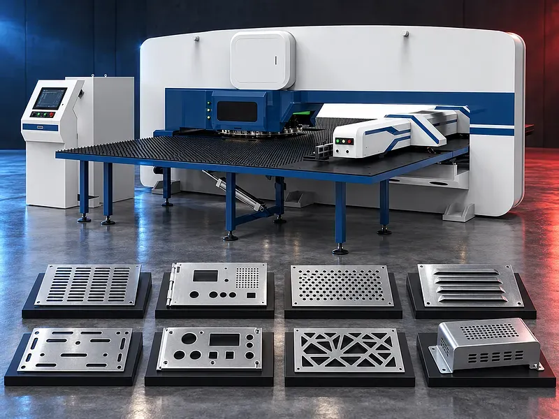
How turret punching works
The sheet is clamped and moved to programmed coordinates. The turret rotates the selected punch and die into alignment, and the press drive completes the stroke to create the required feature.
Part quality and process stability depend on tool geometry, clearance, alignment, stripping, material support, axis positioning, sheet flatness, lubrication, program sequence, and machine condition.
Machine frame and working structure
The frame supports the punching unit, turret, sheet positioning axes, tables, clamps, and guarding. Open and closed frame arrangements can have different access, stiffness, vibration, service, and loading characteristics.
Frame material, welding, stress relief, machining, throat depth, allowable load, deflection basis, vibration control, foundation, and alignment require approved technical confirmation. No frame should be described as having zero deformation.
Turret and tooling stations
The turret stores punches and dies in stations that can differ in size, shape capacity, indexing capability, forming clearance, and tool interface. The CNC selects a station according to the programmed feature.
Turret diameter, station count, station sizes, indexed stations, rotation speed, tool height, alignment, wear plates, lubrication, lifting method, setup time, and included tooling must be confirmed for the exact configuration.
Punches dies and clearance
Each feature requires a compatible punch, die, stripper, and clearance for the material and process. Suitable clearance helps control punching force, burr, slug release, edge condition, tool wear, and sheet deformation.
Tool material, coating, sharpening limits, die clearance, punch penetration, stripper pressure, slug control, lubrication, grind life, storage, identification, and replacement procedure should follow approved tooling instructions.
Punching force and material capacity
Required force depends on material shear strength, thickness, cut perimeter, tool shape, clearance, penetration, stripping, and simultaneous features. Forming tools can introduce additional force and height requirements.
Rated force, usable force through the stroke, overload protection, material limits, maximum tool size, forming capacity, sheet thickness range, and duty conditions must be verified. A stated force alone does not define complete machine capacity.
Punch drive and stroke control
The punching unit may use servo electric, hydraulic, mechanical, or another approved drive arrangement. Drive technology influences stroke profile, force control, speed, energy use, noise, heat, maintenance, and supported forming functions.
Drive type, motor or hydraulic data, stroke length, programmable stroke, acceleration, deceleration, force monitoring, overload response, cooling, lubrication, and duty pattern require exact model confirmation.
Axis drives guides and positioning
CNC axes move the sheet in two directions while feedback systems control position. The drive arrangement may use servo motors, gear systems, racks, ball screws, linear guides, encoders, or other components according to the design.
Axis travel, speed, acceleration, positioning accuracy, repeatability, guide type, drive type, lubrication, compensation, calibration, backlash, protection, and component origin should only be stated from approved documentation.
Clamps repositioning and processing zones
Sheet clamps grip the blank and move it through the punching area. Some systems may include clamp protection, automatic repositioning, programmable release, or avoidance logic to reduce interference between clamps and tools.
Clamp count, grip range, force, marking risk, minimum edge, dead zones, repositioning accuracy, maximum sheet size, sheet mass, collision logic, and any unprocessed areas must be confirmed. Blind spot free processing should not be claimed without verified evidence.
Sheet support and work tables
Brush, ball, roller, or mixed tables may support the sheet while it moves. Suitable support can reduce scratching, sagging, drag, vibration, and positioning disturbance for compatible sheets.
Table dimensions, support type, load, spacing, cleanliness, replaceable elements, noise, friction, coating sensitivity, film handling, sheet overhang, and maintenance should be reviewed for the application.
CNC programming and software
The control and programming system may manage geometry, tool assignment, hit sequence, forming operations, clamps, repositioning, sheet layout, simulation, alarms, corrections, and production records according to the installed software.
Controller type, programming method, supported file formats, drawing import, nesting, tool libraries, collision checking, offline programming, licenses, language, updates, backups, network functions, and data ownership require written confirmation.
Nesting and material utilization
Nesting software can arrange parts on a sheet according to geometry, grain direction, common line rules, tool access, clamps, forming features, skeleton stability, unloading, and downstream requirements.
Material utilization depends on part mix, margins, spacing, remnant policy, repositioning, clamp zones, part removal, scrap bridges, and programming rules. No nesting method guarantees a specific saving without measured comparison.
Punching rate cycle time and output
Punching frequency can vary with stroke length, tool size, material, axis travel, part geometry, turret indexing, forming operations, clamp movement, repositioning, loading, unloading, and control limits.
Maximum strokes per minute should not be treated as finished part output. Verified cycle time requires the actual program, sheet, tool set, loading method, inspection, scrap handling, maintenance, and acceptance conditions.
Energy use and operating efficiency
Electrical consumption depends on drive technology, machine size, punching load, hit rate, axis motion, auxiliaries, cooling, extraction, compressed air, standby time, and production mix.
Any stated energy use needs a defined test method, operating cycle, time period, included auxiliaries, meter location, material, program, and machine condition. Energy saving or environmental claims require approved evidence.
Supported punching and forming operations
Potential operations include round and shaped holes, slots, cutouts, perforation patterns, nibbling, part marking, louvers, embossing, countersinking, knockouts, tabs, bridges, and selected formed features when supported by the machine and tooling.
Every operation should be checked for tool size, force, forming height, sheet support, lower tool clearance, collision, slug control, surface requirement, part removal, and downstream process.
Cut quality and inspection
Inspection may cover hole size and position, pitch, edge distance, burr height, rollover, straightness, flatness, surface marks, form height, angle, cracks, slug pulling, scratches, distortion, and dimensional relationship to bends or assemblies.
The quality plan should define tolerances, datum, measuring equipment, sampling, calibration, first sheet approval, tool wear limits, correction method, nonconforming part handling, traceability, and final acceptance.
Material behavior and sheet flatness
Sheet flatness, residual stress, rolling direction, coating, hardness, thickness variation, protective film, scale, lubrication, and cut edge condition can influence movement, punching force, burr, distortion, and part release.
The incoming material standard and acceptance checks should be agreed. Automatic positioning cannot correct sheets that are outside the approved flatness, thickness, or surface condition.
Automation and part handling
Optional systems may include sheet loading, blank separation, alignment, unloading, sorting, skeleton handling, scrap conveyors, part chutes, robots, storage towers, and production monitoring when supported by the configuration.
Automation should be reviewed for sheet size and mass, separation reliability, part geometry, scratches, micro joints, unstable skeletons, scrap control, cycle interlocks, safety zones, recovery procedures, and integration ownership.
Industrial applications
Potential applications include electrical and industrial enclosures, ventilation parts, perforated panels, brackets, cabinets, shelves, appliance components, elevator parts, lighting products, metal furniture, doors, machinery covers, and general sheet metal fabrication.
Application suitability depends on material, sheet and part dimensions, hole and form geometry, surface finish, tolerances, batch mix, joining and bending sequence, handling, inspection, and the applicable product standard.
How to choose the correct machine
Provide part drawings and flat patterns, material grades and strength, minimum and maximum thickness, sheet dimensions and mass, hole and cutout range, formed features, tolerances, surface requirements, quantities, batch sizes, part mix, and target output.
Also define tool inventory, indexed tool needs, loading and unloading, part and scrap removal, software workflow, file formats, data integration, utilities, floor space, safety rules, shift pattern, maintenance resources, and acceptance trial requirements.
Technical information to verify
Approved documents must confirm frame type, punching force, drive system, sheet capacity, maximum thickness by material, axis travels and speeds, positioning accuracy conditions, turret layout, station count and sizes, indexed stations, maximum tool size, hit rate conditions, and clamp system.
Machine dimensions, weight, electrical supply, measured energy basis, compressed air, cooling, lubrication, extraction, noise test basis, controls, software, file formats, connectivity, guarding, safety functions, automation, standard tools, options, foundation, documentation, training, and acceptance method also require confirmation.
Information supplied for verification
The supplied description refers to specific punching frequency, electrical consumption, punching force, servo components, guide and drive components, frame construction, tooling quantity, software functions, clamp avoidance, and broad availability claims.
These items should not be published as facts until the exact machine datasheet, bill of materials, software specification, energy test method, tooling list, safety documents, and technical review confirm them.
Safety and operating risks
Risks include punch and die crushing, moving sheet and clamps, turret rotation, sharp edges, ejected slugs, tool failure, unstable skeletons, automatic loading, dropped sheets, unexpected restart, stored hydraulic or electrical energy, noise, and maintenance work.
The safety concept should include approved guards, interlocked access, scanners or light curtains where suitable, emergency stops, safe setup mode, tool change controls, loading zones, sheet and scrap management, lockout procedures, inspection, training, supervision, and a documented risk assessment.
Installation and commissioning
Site preparation should cover delivery access, unloading, floor capacity, foundation, anchoring, leveling, electrical isolation, compressed air, cooling or extraction where required, lighting, guarding, sheet routes, loading equipment, scrap handling, tool storage, and maintenance access.
Commissioning should include geometry, turret and tool alignment, axis calibration, clamps, tables, lubrication, drive and control tests, software setup, network and file transfer tests when approved, safety validation, trial programs, sample inspection, training, and document handover.
Maintenance and lifecycle support
Preventive maintenance should follow approved schedules for punches, dies, strippers, turret stations, guides, drives, screws or racks, bearings, lubrication, clamps, tables, hydraulic or pneumatic components, cooling, sensors, controls, guards, interlocks, and emergency systems.
Recommended tools, sharpening equipment, wear parts, seals, filters, lubricants, guide and drive parts, sensors, calibration devices, software backups, licenses, service tools, technical support, training, inspection records, and documents should be agreed for the selected machine.
Limitations and publishing status
The supplied description and infographic do not verify stability, reliability, punching speed, energy consumption, force, component origin, zero deformation, clamp avoidance, file import, automatic nesting, certifications, connectivity, tooling quantity, or availability of all sizes and power levels.
The page needs an approved datasheet for the exact machine, verified performance and energy test conditions, confirmed tooling and software scope, approved image rights, technical review, staging review, and final content approval before publication.
Technical review and next step
Send part drawings and flat patterns, material details, sheet dimensions, hole and form geometry, thickness range, tolerances, quantities, target output, tooling inventory, loading and unloading method, software workflow, file formats, utilities, and site layout for technical review.
The review should compare the part family with approved machine data and identify the suitable press, turret, tool set, software, clamps, automation, inspection, safety concept, acceptance trial, installation, training, maintenance, and spare parts scope.
Questions we are asked
What is a CNC turret punch press?
It is a sheet metal machine that moves a clamped blank beneath indexed punch and die tools to create programmed holes cutouts patterns and supported formed features.
Which operations can it perform?
Potential operations include punching nibbling perforating marking and selected forming features only when the exact machine tool stations material and program support them.
Does the maximum hit rate equal production output?
No. Finished output also depends on axis travel turret indexing forming operations clamps repositioning loading unloading inspection and scrap handling.
Can the stated energy use be accepted directly?
No. Energy data needs an approved test method operating cycle time period included auxiliaries meter location material program and machine condition.
What information is needed for selection?
Provide part drawings flat patterns material strength thickness sheet size hole and form geometry tolerances quantities target output tooling software workflow loading method utilities and site layout.
Tell us the part you need to make
An engineer reads every request. Usually the same working day.
Related
- CNC Hydraulic Press Brake CNC-controlled hydraulic press brakes for bending sheet metal components according to defined angles, dimensions and production requirements.
- CNC TUBE BENDING MACHINE CNC tube bending machines control the bending sequence to produce defined tube and pipe geometries. Selection depends on the material, section, diameter, wall thickness, bend radius, part geometry, accuracy, and production volume.
- CNC Gantry Plasma Cutting Machines A CNC gantry plasma cutting machine moves one or more cutting stations across a guided bridge to process suitable electrically conductive plate and supported profiles. The correct configuration depends on the material, thickness, plate size, part geometry, edge quality, bevels, secondary operations, extraction, automation, and required output.