

CONVENTIONAL METALWORKING MACHINES
Vertical Slotting Machines
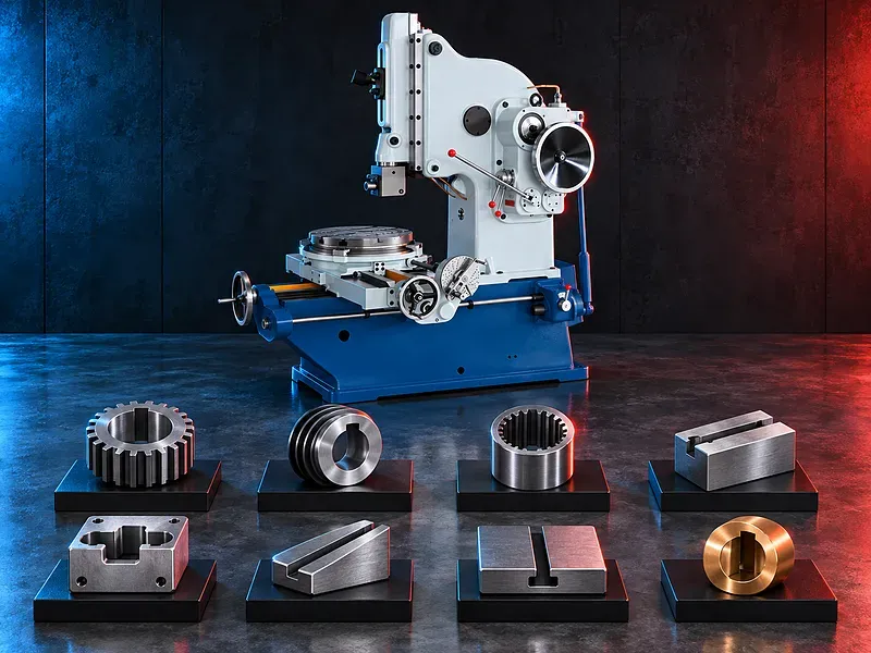
Vertical slotting machines use a reciprocating ram and a single point cutting tool to machine supported internal and external features such as keyways, slots, flat surfaces, and selected formed profiles. Machine selection depends on the part, feature geometry, material, stroke, table movement, tolerance, batch size, and required output
A vertical slotting machine removes material during repeated vertical strokes while the workpiece is secured on the machine table or a suitable fixture. Controlled longitudinal, transverse, or rotary table movement may position the workpiece for internal keyways, slots, flat surfaces, angular features, and selected contours. The supplied description refers to hydraulic ram motion, hydraulic table feed, manual feed, rapid table movement, continuously adjustable speeds, three directions of table feed, and angular work within 10 degrees. These functions and their ranges must be verified from the approved documentation for the exact
How vertical slotting works
A single point cutting tool is mounted on a vertically reciprocating ram. The cutting stroke removes material and the return stroke repositions the tool for the next feed movement according to the machine design and setup.
The workpiece remains secured on the table while controlled table movement presents the next cutting position. Stroke length, ram position, speed, feed, tool geometry, and clearance must suit the feature and material.
Typical machining applications
Potential applications include internal keyways, straight slots, internal splines where supported, square or rectangular internal features, flat surfaces, angular surfaces, and selected formed profiles.
Suitability depends on tool access, feature depth and width, part opening, material, rigidity, fixture clearance, chip evacuation, tolerance, surface finish, and the verified machine capacity.
Longitudinal transverse and rotary table movement
The supplied description states that the worktable provides longitudinal, transverse, and rotary feed. This arrangement may allow several supported surfaces or positions to be machined from one secure clamping when the travels and table geometry suit the component.
The actual travel ranges, feed increments, rapid movement, table diameter, load, graduations, backlash, locking, and position accuracy must be confirmed for the exact model.
Hydraulic ram drive
The supplied description refers to hydraulic transmission for the reciprocating ram. A hydraulic system may provide adjustable stroke motion and controlled reversal when designed and maintained for the duty.
Hydraulic pressure, flow, oil specification, reservoir, filtration, cooling, stroke rate, reversal behavior, leakage limits, and maintenance requirements need verification from the model manual.
Table feed and return stroke timing
The supplied description indicates that hydraulic feed is applied around the ram return transition. Correct feed timing can position the workpiece between cutting strokes and reduce the risk of feeding during active cutting contact.
The feed mechanism, available manual and powered modes, feed direction, feed range, rapid movement, interlocks, and control sequence must be verified before operation.
Ram speed and continuous adjustment
The supplied description states that ram and table movement speeds can be adjusted continuously and that the ram has the same speed in each stroke. The exact speed profile and adjustment method require technical confirmation because cutting and return behavior may vary by design.
Ram speed should match the material, tool geometry, cutting depth, rigidity, lubrication, chip control, and required finish. Productivity claims should be validated on the actual part.
Angular and formed surface work
The supplied description mentions angular work within 10 degrees and machining of formed surfaces. These operations may require ram head adjustment, table rotation, special tool geometry, controlled feed, and a dedicated fixture.
The angle range, reference method, locking, clearance, cutting capacity, and achievable result must be checked against the model documentation and an approved sample when critical.
Tooling and tool setting
Tool selection should consider shank size, holder interface, feature width, depth, corner radius, relief angles, rake, material grade, cutting direction, and available clearance inside the component.
Tool projection should be kept within a stable setup. Tool height, orientation, ram clearance, stroke endpoints, entry, exit, and chip path must be checked before starting the cycle.
Workholding and one setup machining
The fixture should locate the component from suitable datums and resist vertical cutting force, side load, rotation, lifting, and vibration. Clamps must remain outside the ram, tool, chip, and table travel envelopes.
Machining several supported features from one clamping may reduce handling and datum changes, but only when the table movements, fixture rigidity, feature access, and inspection plan support the sequence.
Materials and part suitability
Potential work may include suitable steels, cast irons, nonferrous metals, and other machinable materials after review of grade, hardness, heat treatment, condition, chip behavior, tool material, and lubrication.
Heavy interrupted cuts, very hard materials, deep narrow slots, thin walls, flexible parts, and restricted internal access may require special tooling, reduced cutting data, another process, or a sample trial.
Accuracy surface finish and inspection
Acceptance may cover keyway width and depth, slot position, parallelism, perpendicularity, angular position, profile, corner condition, surface finish, and relationship to the part datums.
Inspection may use calibrated calipers, micrometers, depth gauges, gauge blocks, bore or keyway gauges, indicators, angle measurement, templates, optical methods, or coordinate measurement according to the drawing.
How to choose the correct machine
Provide the part drawing, material grade and hardness, component dimensions and weight, internal opening, keyway or slot width and depth, feature position, angle, tolerance, finish, quantities, batch sizes, and target output.
Selection should review maximum stroke, ram adjustment, distance from tool to table and column, table dimensions and load, longitudinal and transverse travels, rotary movement, feed ranges, ram speeds, tool holder, motor power, hydraulic system, controls, guarding, and floor space.
Technical information to verify
The approved exact model source must confirm the manufacturer, model, maximum slotting length, ram stroke range, ram adjustment, strokes per minute, tool holder dimensions, maximum tool load, table size, table travel, rotary range, table load, and distance dimensions.
It must also confirm hydraulic and manual feeds, rapid movements, speed adjustment method, motor and pump power, hydraulic pressure and oil, electrical supply, angular adjustment range, accuracy test basis, dimensions, weight, foundation, guards, included tooling, and optional equipment.
Safety and operating risks
The risk assessment should cover ram reciprocation, crushing and pinch points, tool breakage, sharp chips, workpiece movement, table travel, hydraulic pressure, hot oil, leakage, manual handling, electrical hazards, unexpected restart, and maintenance isolation.
Required controls may include guards, secure clamping, stroke and clearance checks, emergency stopping, safe chip removal, suitable personal protective equipment, hydraulic hose inspection, training, housekeeping, and documented lockout procedures.
Installation maintenance and lifecycle support
Site planning should confirm floor capacity, foundation and anchoring, leveling, electrical supply, lighting, lifting access, workpiece handling, chip collection, oil containment, ventilation, maintenance clearance, and operator training.
Preventive maintenance should follow approved manufacturer documentation for the ram guides, hydraulic pump and valves, seals, oil and filters, table screws or drives, lubrication, tool holder, controls, alignment, guards, and wear inspection.
Limitations and alternative processes
A conventional vertical slotter is generally suited to single parts, repair work, tooling, and small batches rather than unattended high volume production. Cycle time can increase with deep features, small feeds, hard materials, or complex setup.
Depending on the feature and volume, alternatives may include broaching, keyseating, milling, wire electrical discharge machining, shaping, gear shaping, machining centers, or dedicated tooling.
Technical review and next step
Send component drawings, material and heat treatment data, feature dimensions, datums, tolerances, surface requirements, annual and batch quantities, target output, available utilities, floor plan, and handling method to SAKKARY MACHINERY.
The technical review will compare the application with approved model information and identify the suitable stroke, table movement, tooling, fixture, hydraulic configuration, inspection plan, installation needs, and any sample machining requirement.
Questions we are asked
What is a vertical slotting machine?
It is a machine that uses a vertically reciprocating single point cutting tool to produce supported internal or external slots keyways flat surfaces and selected profiles.
What features can it machine?
Potential features include internal keyways straight slots flat and angular surfaces and selected formed profiles when tool access capacity and workholding are suitable.
Does the table move in three directions?
The supplied description states longitudinal transverse and rotary feed. The actual travels feeds rapid movements and positioning accuracy require exact model verification.
Is the ram hydraulically driven?
The supplied description identifies hydraulic ram motion and hydraulic table feed. Pressure flow control sequence and operating data must be confirmed from the model manual.
Is it suitable for high volume production?
A conventional slotter is commonly considered for individual parts repairs tooling and small batches. Actual output and alternative processes should be compared for the required volume.
What information is required for selection?
Provide part drawings material and hardness feature width depth position and angle tolerances finish quantities target output utilities floor space and handling details.
Tell us the part you need to make
An engineer reads every request. Usually the same working day.
Related
- Heavy-Duty Gap-Bed Conventional Lathes Heavy-duty conventional lathes for turning large-diameter, long, and heavy rotational components. The gap-bed design provides additional swing near the headstock for suitable short workpieces.
- Gantry Type Milling Machine A gantry-type milling machine provides an open working area for machining suitable large or heavy components. Selection depends on workpiece dimensions, weight, material, required operations, tolerances, finish, and production requirements.
- Boring Machine for Workshop Machining A boring machine for drilling, enlarging, finishing, and aligning suitable holes in individual parts and small production batches. The correct model depends on workpiece size, material, hole diameter, depth, tolerance, surface finish, setup, tooling, and required output.