

MILLING MACHINES
Gantry Type Milling Machine
A gantry-type milling machine provides an open working area for machining suitable large or heavy components. Selection depends on workpiece dimensions, weight, material, required operations, tolerances, finish, and production requirements.
A gantry-type milling machine uses a bridge structure positioned over the working area to support the machining head and axis movements. Depending on the verified model, it may be configured for milling, drilling, boring, tapping, or other supported machining operations.
The correct machine must be selected from the component drawing, workpiece dimensions and weight, material, machining envelope, tolerances, surface finish, tooling, and handling requirements. Explore related CNC machines or submit your application for technical review.
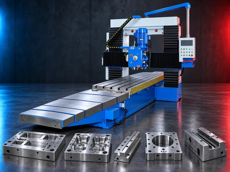
What is a gantry-type milling machine?
A gantry-type milling machine has a bridge structure spanning the work area. The machining head moves within the machine’s verified axis configuration while the workpiece is secured on the table, floor plate, or another approved workholding system.
Typical applications
- Machining large plates and structural components
- Milling machine bases and frames
- Machining dies, molds, and tooling plates
- Producing flat surfaces, pockets, slots, and profiles
- Drilling and boring large components where supported
- Machining welded or cast structures
- Producing large custom components from approved drawings
- Application suitability must be confirmed against the component drawing, workpiece condition, and selected model’s capacity.
- Potential production benefits
- Working area suitable for defined large components
- Access to multiple areas of a secured workpiece
- Programmed machining where fitted with CNC control
- Reduced repositioning for parts within the working envelope
- Support for different heads and tools where available
- Integration with probing and measurement systems where supported
- Accuracy, output, surface finish, and cycle time depend on machine construction, foundation, thermal conditions, workholding, tooling, programming, and the actual application.
How to choose the machine
- Provide a complete component drawing and 3D model where available
- Confirm workpiece dimensions, weight, and center of gravity
- Identify the material and blank condition
- List all milling, drilling, boring, and tapping operations
- Define the required working envelope and clearances
- Confirm dimensional and geometric tolerances
- State the required surface finish
- Define roughing and finishing requirements
- Review spindle speed, power, torque, and interface needs
- Determine the required axes and head configurations
- Review table, floor-plate, fixture, and clamping requirements
- Confirm tool capacity and automatic tool-change requirements
- Define chip, coolant, extraction, and guarding needs
- Plan loading, lifting, and operator access
- Review foundation, power, air, space, and environmental conditions
Technical data to verify
- Manufacturer, brand, model, and country of origin
- CNC or conventional control configuration
- Fixed or moving gantry architecture
- Number and arrangement of controlled axes
- Table or working-area dimensions
- Distance between columns
- Maximum workpiece dimensions and load
- Longitudinal, cross, vertical, and ram travels
- Spindle speed, power, torque, taper, and interface
- Available milling heads and angular positioning
- Tool magazine and automatic tool changer
- Feed rates and rapid movements
- Positioning accuracy and repeatability
- Verified machining tolerances and test conditions
- CNC control, programming, and compensation functions
- Probing and measurement options
- Coolant, chip-conveyor, filtration, and extraction systems
- Dimensions, weight, foundation, utilities, and safety requirements
Machine configuration
Gantry machines may use fixed-gantry, moving-gantry, moving-table, or floor-type arrangements. The appropriate architecture depends on the workpiece size, weight, loading method, production mix, and required accessibility.
Limitations and alternatives
A gantry-type machine may not be the most economical choice for small or simple components. A vertical machining center, horizontal machining center, bed-type mill, floor-type boring mill, or another solution may be more appropriate depending on the application.
Installation and lifecycle support
Installation planning must address foundation design, floor load, leveling, lifting access, machine assembly, electrical supply, compressed air, coolant, chip handling, guarding, environmental conditions, and inspection equipment. Supply, commissioning, training, maintenance, spare parts, tooling, and warranty scope must be confirmed in the approved offer.
Request a technical review
Send the component drawing, material, dimensions, weight, operations, tolerances, finish requirements, and production target. SAKKARY MACHINERY will review the application before recommending a machine configuration.
Questions we are asked
What components are suitable for a gantry-type milling machine?
It may suit large plates, frames, bases, molds, dies, and structural components whose dimensions, weight, and operations fit the verified machine capacity.
What is the difference between fixed and moving gantry designs?
In a fixed-gantry design, the bridge remains fixed while another machine element provides longitudinal movement. In a moving-gantry design, the bridge moves along the work area. Exact architecture varies by model.
What information is required for machine selection?
Provide the component drawing, material, dimensions, weight, operations, tolerances, finish, loading method, and production quantity.
Can the machine perform five-axis machining?
Only models equipped and verified for the required axes, head movements, control functions, and simultaneous machining can support such operations.
What site preparation is required?
Requirements may include an engineered foundation, adequate floor loading, lifting access, electrical supply, compressed air, coolant, chip handling, and suitable environmental conditions.
Tell us the part you need to make
An engineer reads every request. Usually the same working day.
Related
- Heavy-Duty Gap-Bed Conventional Lathes Heavy-duty conventional lathes for turning large-diameter, long, and heavy rotational components. The gap-bed design provides additional swing near the headstock for suitable short workpieces.
- Boring Machine for Workshop Machining A boring machine for drilling, enlarging, finishing, and aligning suitable holes in individual parts and small production batches. The correct model depends on workpiece size, material, hole diameter, depth, tolerance, surface finish, setup, tooling, and required output.
- Double Column Horizontal Bandsaw A horizontal bandsaw with a double column guide structure for controlled cutting of suitable metal bars, tubes, profiles, and billets. The correct model depends on material, section shape, cutting size, bundle arrangement, required finish, batch pattern, automation, and target output.