

BORING AND HOLE MACHINING
Boring Machine for Workshop Machining
A boring machine for drilling, enlarging, finishing, and aligning suitable holes in individual parts and small production batches. The correct model depends on workpiece size, material, hole diameter, depth, tolerance, surface finish, setup, tooling, and required output.
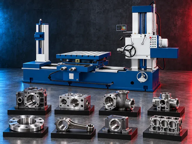
A boring machine removes material from an existing hole to improve its diameter, alignment, position, or finish. Depending on the verified configuration and tooling, the same machine may also perform drilling, reaming, facing, counterboring, spot facing, and related workshop operations. The supplied description refers to a coordinated machine layout, rectangular guideways, hardened guide surfaces, and a digital position display. These construction and control details must be confirmed from the official documentation for the exact model before they are presented as specifications
Machine purpose
The primary purpose of a boring machine is to enlarge and finish an existing hole while controlling its diameter, position, alignment, roundness, and surface condition within the capability of the selected machine, tooling, setup, and inspection method.
The machining plan should begin with the finished component drawing and identify the hole datums, dimensions, tolerances, depths, relationships to other features, surface finish, and downstream assembly requirements.
Suitable production pattern
The described machine is intended for individual parts and small batch production in a machine shop. This may suit repair work, maintenance components, prototypes, tooling, replacement parts, and varied jobs that require flexible setup.
Actual suitability depends on setup time, operator skill, workpiece handling, tooling changes, inspection effort, repeatability, batch size, and the required delivery schedule.
Drilling boring and reaming
Drilling creates a new hole. Boring enlarges or corrects an existing hole with a single point or supported boring tool. Reaming uses a multi edge tool to finish a prepared hole to a controlled size and surface condition.
The correct operation sequence depends on the starting condition, material, stock allowance, depth, diameter, tolerance, finish, rigidity, tool overhang, coolant, and inspection plan.
Potential workpieces and applications
Potential workpieces include machine housings, bearing seats, gearboxes, valve bodies, pump bodies, engine components, flanges, fixtures, welded fabrications, maintenance parts, and other components requiring controlled hole machining.
Every workpiece must be reviewed for overall dimensions, weight, material, casting or welding condition, datum surfaces, access, internal features, interrupted cuts, hardness, required accuracy, and lifting method.
Machine structure and stability
The supplied description states that the machine body, vertical column, and sliding seat use rectangular guideways. A verified rectangular guideway design may provide a broad contact area and structural support for suitable cutting loads.
Guideway geometry alone does not guarantee finished accuracy. Foundation, leveling, lubrication, wear condition, thermal stability, spindle condition, setup rigidity, tool condition, cutting data, and inspection also affect the result.
Guideway hardening and wear control
The supplied description states that the guide surfaces receive an automatic quenching process for wear resistance. The exact material, heat treatment method, hardness range, hardened depth, grinding or scraping process, lubrication system, and acceptance standard require manufacturer evidence.
Long term guideway performance also depends on correct lubrication, contamination control, wiper condition, load distribution, maintenance, alignment checks, and repair practices.
Digital position display
A verified digital readout may display axis position and help the operator approach programmed or drawing dimensions more directly than relying only on manual scale reading.
Display resolution does not equal machining accuracy. Scale installation, backlash, geometry, thermal movement, datum setting, tool deflection, operator method, and inspection equipment must be considered.
Workholding and setup
The workpiece must be located from suitable datums and clamped without distortion. Tables, angle plates, fixtures, clamps, supports, rotary devices, and lifting equipment should be chosen for the component geometry and operation sequence.
The setup plan should control tool access, spindle reach, overhang, chip clearance, coolant flow, collision risks, part movement, datum transfer, and inspection access.
Tooling and cutting process
Potential tooling includes drills, boring bars, boring heads, reamers, facing tools, counterboring tools, adapters, tool holders, supports, and measuring instruments compatible with the verified spindle and machine interface.
Tool selection and cutting data depend on the workpiece material, hardness, hole diameter, depth, stock allowance, interrupted surfaces, tolerance, finish, machine rigidity, spindle capability, coolant, and tool supplier recommendations.
Accuracy and inspection
Finished hole quality may include diameter, roundness, cylindricity, straightness, perpendicularity, concentricity, position, spacing, depth, and surface finish requirements. Only the characteristics specified on the drawing should be accepted.
Inspection may require bore gauges, micrometers, dial indicators, height measurement, alignment bars, surface finish instruments, coordinate measurement, or other calibrated equipment selected for the tolerance and feature.
How to choose the correct machine
Provide component drawings with material, dimensions, weight, hole diameters, depths, spacing, datum relationships, tolerances, surface finish, quantities, batch sizes, and current production route.
Selection should also consider spindle size and taper, spindle travel, table size, table load, axis travels, spindle speeds, feeds, power, facing capability, rotary table requirements, digital readout or control, tooling, coolant, chip management, and floor space.
Technical information to verify
The approved exact model source must confirm the manufacturer, brand, model, machine type, spindle diameter, spindle taper, spindle travel, spindle speed range, feeds, motor power, axis travels, table dimensions, table load, and facing head capability where applicable.
It must also confirm positioning accuracy, repeatability, digital readout axes and resolution, guideway type and hardening, lubrication, coolant, electrical supply, dimensions, weight, foundation, included tooling, guards, safety devices, and stated test conditions.
Coolant chips and workshop environment
The machining process should provide suitable coolant or lubrication where required and a controlled method for collecting chips from holes, fixtures, tables, guideways, and the surrounding area.
Material type, coolant chemistry, chip form, dust, mist, housekeeping, filtration, disposal, corrosion control, and environmental requirements must be considered in the site plan.
Safety requirements
The risk assessment should address rotating spindles and tools, entanglement, sharp chips, hot swarf, coolant, heavy workpieces, lifting, clamping, tool breakage, ejected parts, pinch points, manual handling, and electrical hazards.
The exact guarding, emergency stops, interlocks, operating procedures, personal protective equipment, training, inspection, and maintenance controls must follow the approved machine documentation and site requirements.
Installation and lifecycle support
Site planning should cover machine footprint, foundation, leveling, lifting access, electrical supply, grounding, coolant, lubrication, chip handling, ventilation, lighting, tooling storage, inspection space, maintenance access, and operator training.
The exact supply scope, commissioning, training, preventive maintenance, guideway care, spindle service, consumables, spare parts, warranty, and service commitments require confirmation in the approved technical and commercial offer.
Limitations and alternatives
A boring machine is not automatically suitable for every workpiece, hole size, depth, tolerance, finish, material, batch volume, or production target.
A machining center, jig borer, radial drill, deep hole machine, horizontal machining center, line boring system, portable boring machine, honing machine, or another process may be more suitable for some applications.
Technical review and next step
Send the component drawings with material, dimensions, weight, hole data, tolerances, surface finish, quantities, setup constraints, current process, and target output.
SAKKARY MACHINERY will review the operation sequence, machine size, spindle and table requirements, tooling, workholding, inspection, utilities, safety needs, and information that still requires manufacturer verification.
Questions we are asked
What does a boring machine do?
It enlarges and finishes an existing hole to improve supported dimensions alignment position and surface condition using suitable tooling and setup.
Can the machine drill and ream holes?
The supplied description states that drilling boring and reaming can be performed. The exact operation range tooling and accuracy must be confirmed for the selected model.
Is the machine suitable for small batch work?
The described application is individual parts and small batches. Suitability depends on part size setup time tooling inspection and required output.
What is the value of rectangular guideways?
A verified rectangular guideway design may provide broad support for suitable cutting loads but finished accuracy also depends on condition lubrication geometry setup tooling and inspection.
Does the digital display guarantee accuracy?
No. It helps display axis position but finished accuracy also depends on machine geometry backlash thermal movement setup tool deflection and measurement.
What information is required for selection?
Provide drawings material dimensions weight hole diameters depths tolerances surface finish quantities setup constraints and target output.
Tell us the part you need to make
An engineer reads every request. Usually the same working day.
Related
- Heavy-Duty Gap-Bed Conventional Lathes Heavy-duty conventional lathes for turning large-diameter, long, and heavy rotational components. The gap-bed design provides additional swing near the headstock for suitable short workpieces.
- Gantry Type Milling Machine A gantry-type milling machine provides an open working area for machining suitable large or heavy components. Selection depends on workpiece dimensions, weight, material, required operations, tolerances, finish, and production requirements.
- Double Column Horizontal Bandsaw A horizontal bandsaw with a double column guide structure for controlled cutting of suitable metal bars, tubes, profiles, and billets. The correct model depends on material, section shape, cutting size, bundle arrangement, required finish, batch pattern, automation, and target output.