

SQUARE COLUMN HOLE MACHINING
Vertical Drilling and Tapping Machines
Square column vertical drilling and tapping machines support suitable drilling tapping countersinking spot facing boring and reaming operations in workshop and production environments. The correct machine depends on the workpiece material hole and thread requirements table and spindle geometry feeds tooling fixture duty pattern and required accuracy.
A vertical drilling and tapping machine positions the workpiece on a table beneath a vertical spindle. The spindle carries compatible drills taps reamers countersinks counterbores and boring tools while the quill or head provides the controlled axial movement required by the operation. The supplied description refers to automatic spindle reversal for tapping fine feed a wide speed range high efficiency high accuracy and low noise. These functions and performance claims require verification for the exact model. Selection should be based on part drawings material hardness hole diameters depths positions thread sizes and pitches tolerances finish quantities setup and utilities.
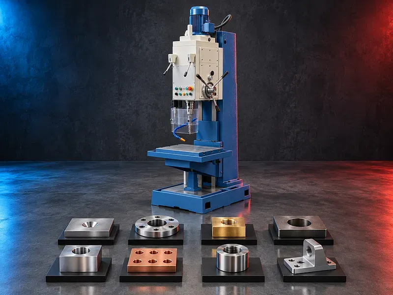
Vertical drilling concept
The spindle rotates the selected tool while the quill head or table movement feeds the tool along the hole axis. The workpiece remains secured to the table or fixture during cutting.
Machine geometry spindle condition feed control workholding tool runout cutting data coolant chip evacuation and inspection affect the finished hole.
Square column structure
A square column can guide the head or supporting structure and may provide a stable path for vertical positioning according to the machine design.
Column size and appearance alone do not prove rigidity or accuracy. Guideway design contact condition locks gibs lubrication foundation and head extension should be reviewed.
Drilling operations
Potential drilling work includes center drilling pilot drilling through holes blind holes stepped holes and selected deep holes when the spindle feed tooling coolant and chip evacuation support the task.
Each hole should be reviewed for diameter depth aspect ratio position tolerance surface requirement breakthrough condition and remaining wall thickness.
Tapping operations
The tapping cycle should coordinate spindle rotation feed depth reversal and withdrawal with a compatible tap and holder. Automatic spindle reversal may support repeat operation when verified for the model.
Blind holes need bottom clearance and controlled chip direction while through holes need safe exit clearance. Correct drill size entry chamfer lubrication speed and torque remain essential.
Countersinking and spot facing
Countersinking forms a conical entry or seating feature while spot facing creates a local flat seat around a hole. Counterboring creates a cylindrical stepped recess according to the drawing.
Tool angle diameter pilot condition depth surface finish concentricity and remaining material should be defined before machining.
Reaming and boring
Reaming can finish a prepared hole to a controlled size and surface condition with a small machining allowance. Boring can correct or enlarge a hole using a supported single point or head arrangement.
Starting hole quality alignment allowance rigidity tool runout feed coolant and measurement method influence the result.
Fine feed and depth control
Fine feed may support controlled boring reaming spot facing or other finishing operations when provided by the model. Depth stops scales or digital displays may assist repeat positioning.
Feed values display resolution and stop settings do not directly prove machining accuracy. Mechanical backlash load deflection thermal effects and tool geometry remain important.
Speed range and spindle drive
Spindle speed should match tool diameter material cutting speed operation and coolant. Gear belt variable speed or electronic drives may be used according to the verified design.
The usable speed and torque under load should be checked. A wide nominal speed range does not confirm performance for every drilling tapping or boring operation.
Spindle taper and toolholding
Potential holders include drill chucks taper shanks collets tapping holders boring heads and adapters compatible with the spindle interface and duty.
Taper condition cleanliness retention runout holder overhang and tool change method affect accuracy rigidity and safety. The exact interface requires model verification.
Table fixture and workholding
Workholding may include vises clamps T slot fixtures angle plates V blocks nests and dedicated jigs selected for part geometry cutting force and datum control.
The setup should prevent movement lifting rotation and distortion while preserving tool access chip flow table travel and inspection access. Hand holding a workpiece during drilling or tapping is unsafe.
Materials and applications
Potential materials may include supported steels stainless steels cast iron aluminum brass and other machinable metals after review of grade hardness condition and chip behavior.
Potential applications include plates brackets housings flanges fixtures machine parts repair parts connectors valves and other components requiring controlled holes and threads.
Coolant lubrication and chips
Suitable coolant or tapping lubricant may control heat reduce friction improve chip evacuation support tool life and protect surface quality when compatible with the material and process.
Blind and deep holes require particular chip control. Chips should not accumulate around the tool fixture table column guards or electrical components.
Hole and thread inspection
Acceptance may include hole diameter depth position perpendicularity straightness roundness surface condition counterbore or countersink dimensions thread size pitch class depth and entry condition.
Inspection may use calibrated plug gauges thread gauges depth gauges bore gauges fixtures optical methods or coordinate measurement according to the drawing and quality plan.
How to choose the correct machine
Provide component drawings material grade hardness dimensions weight hole diameters depths positions thread standards sizes pitches depths tolerances finish quantities batch size setup constraints and target output.
Selection should consider drilling and tapping capacity table dimensions and load spindle taper speed and torque quill diameter and travel feed ranges fine feed reversal method head travel throat distance column geometry motor power coolant DRO fixture area guards utilities and floor space.
Technical information to verify
The approved exact model source must confirm manufacturer brand model construction drilling capacity by material and conditions tapping capacity spindle taper speed range feed range quill travel spindle power torque tapping reversal method and fine feed function.
It must also confirm table size load and travel spindle to table and column distances head movement accuracy test standard coolant lubrication electrical supply dimensions weight foundation guards safety devices included tooling noise test basis and optional equipment.
Cycle time and productivity
Actual output depends on part loading clamping tool changes spindle speed feed hole depth pecking chip removal tapping reversal inspection and downtime rather than machine speed alone.
Productivity and accuracy claims should be verified through an approved sample using the actual part material tools fixture tolerance and operator method.
Safety requirements
The risk assessment should address rotating spindles drills taps and holders entanglement loose chuck keys tool breakage sharp and hot chips ejected workpieces quill and head movement pinch points coolant noise and electrical hazards.
Guards emergency stops secure workholding chuck key control safe setup zones spindle stop procedures operating instructions training personal protective equipment isolation and maintenance controls must follow approved documentation and site requirements.
Installation maintenance and support
Site planning should cover foundation or floor capacity leveling anchoring lifting route electrical supply grounding coolant lubrication chip collection lighting ventilation tooling storage inspection space operator access and maintenance clearance.
Preventive maintenance should cover spindle and quill bearings gears belts feeds guideways screws gibs locks table coolant lubrication electrical controls guards geometry and alignment. Supply scope training spare parts warranty and service commitments require approved confirmation.
Limitations and alternative processes
A vertical drilling and tapping machine is not automatically suitable for every material hole diameter depth position tolerance thread size duty cycle or output target.
A bench drill radial drill milling machine jig boring machine tapping center CNC machining center multi spindle machine or another process may be more suitable for large parts complex patterns tighter positioning automation or higher volume.
Technical review and next step
Send component drawings with material hardness hole and thread data tolerances finish quantities fixture concept current process utilities and target output.
SAKKARY MACHINERY will review machine capacity spindle and feed requirements tooling workholding cycle inspection utilities safety alternatives and information that still requires manufacturer verification.
Questions we are asked
What is a vertical drilling and tapping machine?
It is a workshop or production machine with a vertical spindle used for supported drilling tapping countersinking spot facing boring reaming and related hole operations.
Can it tap blind and through holes?
Potentially yes when the verified reversal depth feed torque tool holder chip control and bottom or exit clearance support the thread requirement.
What is automatic spindle reversal?
It is a verified function that reverses spindle rotation during the tapping cycle so the tap can withdraw after reaching the controlled depth.
What is fine feed used for?
Fine feed may support controlled boring reaming spot facing and other finishing operations when provided and verified for the model.
Does a wide speed range guarantee suitability?
No. The usable speed torque power feed tooling rigidity workholding material and hole requirement must be reviewed together.
What information is required for selection?
Provide part drawings material hardness hole diameters depths positions thread sizes pitches depths tolerances finish quantities fixture concept and target output.
Tell us the part you need to make
An engineer reads every request. Usually the same working day.
Related
- Heavy-Duty Gap-Bed Conventional Lathes Heavy-duty conventional lathes for turning large-diameter, long, and heavy rotational components. The gap-bed design provides additional swing near the headstock for suitable short workpieces.
- Gantry Type Milling Machine A gantry-type milling machine provides an open working area for machining suitable large or heavy components. Selection depends on workpiece dimensions, weight, material, required operations, tolerances, finish, and production requirements.
- Boring Machine for Workshop Machining A boring machine for drilling, enlarging, finishing, and aligning suitable holes in individual parts and small production batches. The correct model depends on workpiece size, material, hole diameter, depth, tolerance, surface finish, setup, tooling, and required output.