

CONVENTIONAL DRILLING MACHINES
Vertical Drilling Machines
Vertical drilling machines support controlled hole making and related workshop operations with the spindle moving toward the workpiece on a vertical axis. The correct machine depends on the part material, dimensions, hole requirements, tooling, batch size, and required output.
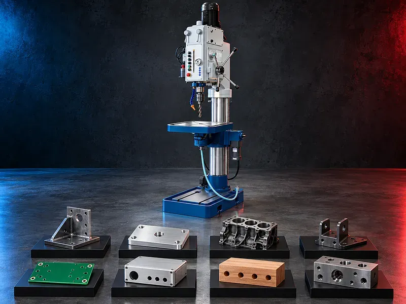
A vertical drilling machine is a general workshop and production machine used for supported drilling, reaming, countersinking, counterboring, spot facing, and tapping operations. The workpiece is secured on the table or a suitable fixture while the spindle and cutting tool move vertically toward the required position. Bench and floor standing configurations may be available, but capacity, spindle interface, speed and feed ranges, table travel, controls, cooling, digital indication, and safety systems vary by model. SAKKARY MACHINERY reviews the part drawings and operating conditions before recommending a configuration.
How a vertical drilling machine works
The spindle is arranged vertically and carries the selected tool toward a workpiece secured on the table or fixture. The operator aligns the hole position, selects the verified speed and feed, controls the cutting cycle, and inspects the result against the drawing.
A vertical layout supports direct access to many small and medium components, but actual part size, weight, reach, table capacity, and lifting needs must be checked for the exact machine.
Supported operations
Potential operations include center drilling, drilling through or blind holes, reaming, countersinking, counterboring, spot facing, tapping, and limited supported boring. Each operation needs suitable tooling, spindle capability, workholding, cutting data, lubrication, and inspection.
The exact operations and capacities must be confirmed from the approved documentation for the selected model.
Bench and floor standing configurations
A bench mounted machine can suit compact parts and lighter workshop tasks when the verified capacity and stability meet the application. A floor standing pillar or column machine may provide a larger working envelope and support heavier components according to its approved design.
Configuration should be selected from part dimensions and weight, hole position, operator access, table movement, fixture space, material flow, and available floor area.
Spindle speed feed and depth control
Cutting speed and feed should match the tool diameter, material, operation, depth, cooling method, and required result. Depending on the model, adjustment may be mechanical, stepped, variable, or electronically controlled.
A depth stop may support repeatable hole depth when correctly set and maintained. Digital readouts, power feed, fine feed, and automatic functions are model dependent and require verification.
Table movement and workholding
The table may provide height adjustment and other movement according to the machine design. A vise, clamps, angle plate, V block, fixture, or dedicated jig should locate and restrain the component against cutting forces.
The workpiece must not be held by hand during machining. The fixture should preserve tool access, chip clearance, inspection access, and safe loading while preventing movement, lifting, rotation, and distortion.
Tooling and spindle interface
Potential tooling includes drill chucks, taper shank drills, collets, tapping holders, reamers, countersinks, counterbores, spot facing tools, boring tools, and compatible adapters.
Spindle taper, tool capacity, retention method, runout, holder projection, torque transmission, and tool change procedure must be confirmed for the exact model and process.
Materials and component applications
Potential work may include suitable metal, plastic, wood, and other machinable materials when the machine, tooling, speed, feed, cooling, guarding, dust or chip control, and workplace rules support the application.
Industrial examples may include plates, brackets, frames, housings, flanges, machine parts, maintenance components, fixtures, and training pieces. Every material and component should be reviewed from its drawing, grade, hardness, condition, and acceptance requirements.
Coolant lubrication and chip control
Suitable coolant or cutting lubricant may help manage heat, friction, chip evacuation, tool life, and surface condition when compatible with the material and operation. Some models may include a coolant system while others require a separate method.
Chips must be controlled and removed using approved procedures. Blind and deep holes may need planned chip evacuation, while combustible dust and reactive materials require a dedicated safety review.
Hole quality and inspection
Acceptance may cover diameter, depth, position, perpendicularity, straightness, roundness, surface condition, entry and exit condition, counterbore or countersink dimensions, and thread size and depth.
Inspection may use calibrated calipers, micrometers, plug gauges, depth gauges, thread gauges, bore gauges, fixtures, optical systems, or coordinate measurement according to the drawing and quality plan.
Production consistency
A stable machine setup, correct tooling, secure workholding, controlled cutting data, trained operation, and planned inspection can support consistent results across a batch.
Accuracy, repeatability, cycle time, tool life, output, and cost per part cannot be confirmed from the machine category alone. They should be validated using the selected model and an approved sample or acceptance method.
How to choose the correct machine
Provide part drawings, material grades, hardness, part dimensions and weight, hole diameters, depths and positions, thread details, tolerances, finish requirements, quantities, batch sizes, fixture concept, shift pattern, and target output.
Selection should review drilling and tapping capacities, spindle taper, speed and feed ranges, quill travel, throat distance, column clearance, table dimensions and load, motor power, cooling, controls, guarding, floor space, utilities, and future work.
Technical information to verify
The approved exact model source must confirm the manufacturer, model, construction, drilling and tapping capacities, spindle taper, spindle travel, throat distance, distances to the table and base, column diameter, table dimensions, table movement, and allowable loads.
It must also confirm spindle speeds, feed ranges, motor power, electrical supply, coolant system, digital display, automatic functions, guarding, noise test basis, dimensions, weight, foundation, included tooling, optional equipment, and stated accuracy conditions.
Safety and operator protection
The risk assessment should address rotating tools, entanglement, ejected chips, sharp swarf, workpiece movement, tool breakage, coolant exposure, pinch points, manual handling, noise, electrical hazards, and maintenance isolation.
Required controls may include guards, emergency stops, secure clamping, approved tools, safe chip removal, suitable personal protective equipment, training, housekeeping, and documented lockout procedures. Exact provisions depend on the model and site requirements.
Installation maintenance and lifecycle support
Site planning should confirm floor capacity, leveling, anchoring when required, electrical supply, lighting, access, material handling, chip and coolant management, storage, ventilation, maintenance clearance, and operator training.
Preventive maintenance should follow approved manufacturer documentation for the spindle, bearings, belts or gears, feeds, table and column surfaces, lubrication, coolant, guards, electrical controls, alignment, and wear inspection. Spare parts and service requirements should be reviewed before purchase.
Limitations and alternatives
A conventional vertical drill generally requires manual part positioning and is not automatically suitable for angled holes, very large workpieces, simultaneous multi hole production, or complex programmed machining.
Depending on the application, a radial drilling machine, multi spindle machine, tapping arm, milling machine, machining center, or custom production system may provide a better solution.
Technical review and next step
Send component drawings, material information, annual and batch quantities, hole and thread requirements, quality criteria, available utilities, floor space, and target output to SAKKARY MACHINERY.
The technical review will compare the application with approved model information and identify the suitable configuration, tooling, fixtures, inspection plan, installation needs, and any points requiring a sample trial.
Questions we are asked
What is a vertical drilling machine?
It is a machine with a vertically arranged spindle used for supported drilling and related hole making operations on a securely fixed workpiece.
What operations can it perform?
Potential operations include drilling reaming countersinking counterboring spot facing tapping and limited supported boring when the selected model tooling and setup are suitable.
Can it machine metal wood and plastic?
Potentially yes but each material requires compatible tooling cutting data cooling or dust control guarding and a verified machine configuration.
What is the difference between bench and floor models?
Bench models generally serve smaller work while floor standing models may provide a larger working envelope. Exact capacity stability and table limits depend on the model.
Does a depth stop guarantee hole accuracy?
No. It can support repeated depth settings but final accuracy also depends on machine condition tooling workholding material cutting data thermal effects and inspection.
What information is needed for selection?
Provide drawings materials part dimensions and weight hole and thread details tolerances quantities fixture concept utilities floor space and target output.
Tell us the part you need to make
An engineer reads every request. Usually the same working day.
Related
- Heavy-Duty Gap-Bed Conventional Lathes Heavy-duty conventional lathes for turning large-diameter, long, and heavy rotational components. The gap-bed design provides additional swing near the headstock for suitable short workpieces.
- Gantry Type Milling Machine A gantry-type milling machine provides an open working area for machining suitable large or heavy components. Selection depends on workpiece dimensions, weight, material, required operations, tolerances, finish, and production requirements.
- Boring Machine for Workshop Machining A boring machine for drilling, enlarging, finishing, and aligning suitable holes in individual parts and small production batches. The correct model depends on workpiece size, material, hole diameter, depth, tolerance, surface finish, setup, tooling, and required output.