

THREAD FORMING MACHINES
QJ 80 External Thread Rolling Machine
The QJ 80 is presented as an external thread rolling machine for forming supported threads and profiles by controlled material displacement. Final suitability depends on the workpiece material, blank dimensions, thread form, length, dies, rolling method, quality requirements, batch size, and verified machine capacity.
External thread rolling is a forming process in which hardened dies press a compatible workpiece surface so the material flows into the required thread or profile shape. Unlike thread cutting, the process does not intentionally remove the thread form as chips, but the material and blank must have suitable forming behavior. The uploaded image identifies the machine as QJ 80 and shows a thread rolling machine with an operator control panel, rolling area, and separate hydraulic power unit. Diameter range, rolling pressure, spindle speeds, die dimensions, pump powers, accuracy, productivity, and all application claims shown in the image require confirmation from an approved official datasheet before publication.
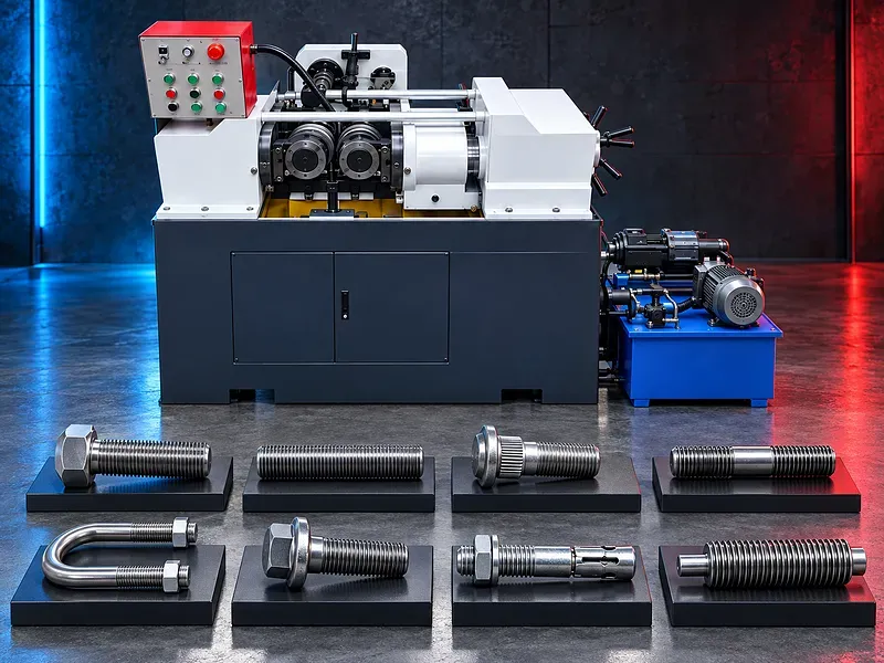
External thread rolling principle
Thread rolling forms the workpiece surface between profiled dies under controlled force and motion. Material is displaced from the thread root toward the crest to create the required external form when the blank and material are suitable.
The process plan must define thread standard, pitch, profile, major and minor diameters, effective diameter, length, runout, entry, tolerance, surface condition, and inspection method.
Rolling method and machine configuration
Thread rolling machines may use infeed, through feed, tangential, or other forming methods according to their construction and tooling. The workpiece may be supported between dies, on a support blade, with centers, or by a dedicated loading arrangement.
The exact method supported by QJ 80, number and movement of dies, work support, cycle sequence, manual or automatic loading, and suitable part families must be confirmed from the official model documentation.
Materials and formability
Potential materials include compatible grades of steel, stainless steel, aluminum, copper alloys, and other ductile metals when their strength, hardness, elongation, surface condition, heat treatment, and forming response meet the process requirements.
Brittle materials, excessive hardness, unsuitable coatings, surface defects, incorrect heat treatment, and poor blank preparation can cause cracking, incomplete fill, scale damage, excessive force, or die wear. Each grade needs technical review and may require a sample trial.
Thread and profile applications
Potential components may include bolts, screws, threaded rods, fasteners, studs, shafts, pins, automotive parts, construction hardware, and other supported cylindrical parts that need an external thread or rolled profile.
The image includes application examples, but suitability for a specific component must be verified from its drawing, material, blank size, formed length, thread standard, tolerance, quantity, and downstream assembly.
Blank diameter and preparation
The starting blank diameter is normally selected in relation to the required thread geometry and material flow, not simply equal to the final major diameter. Blank size must be controlled through an approved process plan or tooling recommendation.
Preparation may include cutting to length, turning, centerless grinding, chamfering, deburring, cleaning, heat treatment, coating removal, and dimensional inspection according to the part and rolling method.
Rolling dies and tooling
The rolling dies must match the required thread standard, pitch, profile, direction, diameter range, material, formed length, rolling method, and machine interface. Die material, hardness, surface condition, and manufacturing accuracy affect the process.
Die outside diameter, bore, width, key or drive arrangement, matching set, permitted speed, mounting direction, setup marks, regrinding limits, and replacement criteria require confirmation from the approved tooling and machine documents.
Hydraulic rolling force
A hydraulic system may control die approach and rolling force according to the machine design. Pressure and motion should be set for the material, blank, profile, die geometry, support, and required result.
The rolling force value shown in the image is not approved technical evidence. Maximum force, working pressure, adjustment range, cylinder arrangement, valves, pump, oil specification, filtration, cooling, and protection settings must be verified from the official QJ 80 manual.
Spindle speed and synchronization
Spindle speed should suit the die diameter, workpiece material, thread pitch, rolling method, lubrication, loading method, and cycle duty. Where more than one spindle or die is driven, correct synchronization and mechanical condition are essential.
The speed values shown in the image require official verification. Actual settings should follow the approved process sheet and remain within the tool and machine limits.
Lubrication cooling and cleanliness
Suitable process fluid may reduce friction, manage heat, support material flow, protect the dies, wash away contamination, and help maintain a consistent surface when compatible with the material and downstream process.
Fluid type, concentration, flow, filtration, cleanliness, tank care, pump capacity, contamination control, and disposal should follow the manufacturer, tooling supplier, material, and site requirements.
Work support feeding and handling
The workpiece must be supported and presented to the dies without uncontrolled movement, misalignment, bending, or interference. Long or flexible parts may need guides, rests, centers, loading trays, or dedicated automation.
Part length, weight, straightness, center condition, entry chamfer, minimum grip, formed position, loading orientation, unloading, and operator reach should be reviewed for every component family.
Thread quality and inspection
Acceptance may cover major diameter, minor diameter, effective diameter, pitch, lead, flank angle, thread form, length, runout, roundness, surface condition, cracks, laps, incomplete fill, and assembly fit.
Inspection may use calibrated thread ring gauges, pitch diameter methods, optical systems, profile measurement, diameter gauges, surface inspection, crack detection where required, and functional assembly tests according to the drawing and quality plan.
Setup repeatability and productivity
Consistent production depends on controlled blank preparation, die condition, setup, alignment, support, hydraulic settings, speed, lubrication, loading, inspection, and preventive maintenance.
Claims for high productivity, accuracy, tool life, cycle time, scrap reduction, or cost per part require validation on the actual component using approved sample trials and acceptance criteria.
How to choose the correct machine
Provide the part drawing, material grade and heat treatment, starting blank diameter, final thread or profile standard, pitch, direction, diameters, formed length, tolerance, surface requirement, part length and weight, quantities, batch size, and target output.
Selection should review rolling method, diameter and length capacity, rolling force, die interface and dimensions, spindle speed, work support, loading, hydraulic system, lubrication, cooling, controls, guarding, inspection, utilities, floor space, and future part range.
Technical information to verify
An approved official QJ 80 source must confirm the manufacturer, exact model designation, rolling method, suitable materials and applications, minimum and maximum work diameter, maximum rolling length, thread pitch range, rolling force, spindle number, and spindle speeds.
It must also confirm die outside diameter, bore, width and interface, work support, hydraulic pump and motor data, cooling pump data, electrical supply, controls, lubrication, guarding, cycle modes, dimensions, weight, foundation, included tooling, optional equipment, stated accuracy, test conditions, and production basis.
Safety and operating risks
The risk assessment should cover rotating dies, drawing in and crushing zones, hydraulic pressure, stored energy, workpiece ejection, die breakage, sharp parts, process fluid, manual handling, electrical hazards, unexpected startup, and maintenance isolation.
Required controls may include fixed and movable guards, interlocks where provided, emergency stops, secure work support, approved dies, safe loading tools, pressure checks, suitable personal protection, training, housekeeping, and documented lockout procedures.
Installation maintenance and lifecycle support
Site planning should cover foundation and floor load, leveling and anchoring, electrical supply, hydraulic oil, process fluid, drainage, ventilation, lifting and die handling, loading space, finished part flow, maintenance clearance, and operator training.
Preventive maintenance should follow approved manufacturer documents for spindles, shafts, bearings, guides, hydraulic pump and valves, seals, oil and filters, lubrication, cooling, controls, guards, alignment, die mounting surfaces, and wear inspection.
Limitations and alternative processes
Thread rolling requires a formable material, controlled blank geometry, suitable access, dedicated dies, and process development. It may not suit brittle materials, very hard finished parts, low quantities that cannot justify tooling, restricted profiles, or components that would distort under forming load.
Depending on the part, alternatives may include thread cutting on a lathe, die head threading, thread chasing, thread milling, tapping for internal threads, grinding, or another cold forming process.
Technical review and next step
Send the part drawing, thread standard, material certificate, heat treatment, blank dimensions, formed length, tolerance, surface requirement, annual and batch quantities, target output, available utilities, floor plan, and handling method to SAKKARY MACHINERY.
The technical review will compare the application with approved QJ 80 documentation and identify material suitability, process method, blank preparation, dies, support, lubrication, inspection, installation needs, and any sample rolling requirement.
Questions we are asked
What is an external thread rolling machine?
It is a forming machine that uses profiled dies and controlled force to displace compatible workpiece material into an external thread or supported profile.
Does thread rolling remove metal as chips?
The intended thread form is created by material displacement rather than cutting. Blank preparation and unsuitable material can still produce scale debris or defects that require control.
Which materials can be rolled?
Only materials with suitable formability hardness surface condition and heat treatment should be considered. The exact grade and condition require technical review and may need a sample trial.
What is the confirmed capacity of QJ 80?
The uploaded image displays model specifications but image text is not an approved technical source. Capacity force speeds and die dimensions require an official datasheet or manual.
What controls thread quality?
Blank diameter material dies alignment support rolling force speed lubrication machine condition and inspection method all affect the result.
What information is required for selection?
Provide the drawing thread standard material and heat treatment blank dimensions formed length tolerance surface requirements quantities target output utilities floor plan and handling method.
Tell us the part you need to make
An engineer reads every request. Usually the same working day.
Related
- Heavy-Duty Gap-Bed Conventional Lathes Heavy-duty conventional lathes for turning large-diameter, long, and heavy rotational components. The gap-bed design provides additional swing near the headstock for suitable short workpieces.
- Gantry Type Milling Machine A gantry-type milling machine provides an open working area for machining suitable large or heavy components. Selection depends on workpiece dimensions, weight, material, required operations, tolerances, finish, and production requirements.
- Boring Machine for Workshop Machining A boring machine for drilling, enlarging, finishing, and aligning suitable holes in individual parts and small production batches. The correct model depends on workpiece size, material, hole diameter, depth, tolerance, surface finish, setup, tooling, and required output.