

CONVENTIONAL METAL MACHINING
Mechanical Shaping Machine
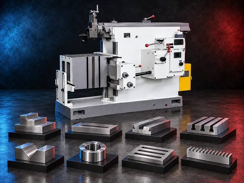
A mechanical shaping machine for machining suitable flat surfaces, steps, slots, keyways, and selected angular features with a reciprocating single point cutting tool. The correct model depends on workpiece size, material, stroke requirement, table capacity, feature geometry, finish, tolerance, and production pattern.
A mechanical shaper moves a single point cutting tool back and forth over a clamped workpiece. Material is normally removed during the cutting stroke, while the return stroke repositions the ram for the next feed movement according to the machine design and setup. This machine type can support flexible workshop operations on suitable individual parts and small batches, but its suitability must be evaluated against milling, slotting, planing, broaching, and other alternatives. Stroke length, ram speeds, feed ranges, table movement, capacity, power, and accuracy require verification for the exact model.
Mechanical shaping process
The ram carries a single point tool through a reciprocating path. The tool removes a controlled layer of material during the cutting stroke and clears the surface during return, while the workpiece or table receives an incremental feed between strokes.
The exact cutting direction, return mechanism, feed timing, stroke adjustment, speed steps, and automatic functions depend on the verified machine design.
Potential machining operations
Potential operations include horizontal flat surfaces, vertical surfaces, stepped faces, shoulders, straight slots, keyways, grooves, selected angular surfaces, and simple formed profiles when supported by the tool head, table, and setup.
Every feature should be reviewed for tool access, stroke clearance, workpiece support, clamping, feed direction, tool lift on return, chip escape, tolerance, surface finish, and inspection method.
Suitable workpieces and applications
Potential workpieces include machine brackets, bases, blocks, slide components, guide parts, fixtures, repair components, keys, small fabrications, and other parts requiring accessible linear surfaces or slots.
Potential uses include maintenance workshops, toolrooms, repair production, training workshops, prototype work, and small batch machining where setup flexibility is more important than high volume automation.
Workpiece materials
Potential materials may include suitable grades of steel, cast iron, nonferrous metals, and other machinable materials compatible with the verified machine rigidity, tooling, cutting speed, and coolant or lubrication method.
Material grade, hardness, casting skin, scale, welded areas, interrupted cuts, inclusions, heat treatment, and required finish must be reviewed before confirming the cutting process.
Mechanical drive and ram movement
A mechanical shaper uses a mechanical transmission to generate the ram motion. Depending on the verified design, the system may use gears, a crank mechanism, a quick return arrangement, speed changes, and mechanical feed components.
The actual mechanism, available speeds, stroke timing, speed change procedure, lubrication, overload protection, and maintenance requirements must be confirmed from the exact machine documentation.
Stroke adjustment and clearance
The stroke should cover the machined feature with sufficient approach and exit clearance while avoiding unnecessary travel. Ram position and stroke length must be set to prevent collision with the workpiece, fixture, table, or machine structure.
The permitted stroke range, ram adjustment method, maximum distance to the table, tool head travel, and clearances are model specific and must be matched to the workpiece drawing.
Workholding and table setup
The workpiece must be located from suitable datums and clamped securely without distortion. A machine vise, clamps, parallels, angle plates, fixtures, supports, or a rotary arrangement may be required according to the component geometry.
The setup should control tool access, ram clearance, table travel, overhang, cutting force, chip flow, return stroke clearance, datum transfer, and inspection access.
Cutting tools and tool head
Single point tools should be selected for the workpiece material, operation, depth of cut, feed, speed, finish, rigidity, and machine capability. Tool material and geometry may vary between roughing, finishing, slotting, and angular work.
The clapper or tool lifting arrangement should allow the tool to clear the workpiece during the return stroke where required. Tool overhang should be controlled to reduce vibration and deflection.
Cutting data and productivity
Ram speed, stroke length, feed per stroke, depth of cut, tool geometry, and the number of passes determine cutting time and tool loading. Settings should follow material and tooling recommendations within the verified machine limits.
Actual productivity, labor requirement, tool life, setup time, cost per part, and finish depend on the component, stroke, cutting data, operator method, inspection, maintenance, and batch pattern.
Quality and inspection
The acceptance plan may include flatness, straightness, parallelism, perpendicularity, slot width and depth, keyway position, angular accuracy, dimensions, and surface finish.
Finished quality depends on machine geometry, guide condition, ram stability, table alignment, workholding, tool condition, tool deflection, cutting data, thermal effects, and calibrated inspection equipment.
How to choose the correct machine
Provide component drawings with material, hardness, overall dimensions, weight, surface or slot length, width, depth, angle, tolerances, finish, quantities, batch sizes, and current production route.
Selection should also consider maximum ram stroke, stroke speed range, table dimensions, table travels, table load, distance between ram and table, tool head adjustment, feed ranges, motor power, lubrication, guarding, and floor space.
Technical information to verify
The approved exact model source must confirm the manufacturer, brand, model, machine type, maximum stroke length, stroke speed range, ram position adjustment, tool head travel, tool head angle, table dimensions, table travels, and table load.
It must also confirm feed ranges, maximum distance between ram and table, motor power, drive mechanism, quick return system, lubrication, accuracy or test standard, electrical supply, dimensions, weight, foundation, included accessories, guards, and safety devices.
Lubrication chip control and housekeeping
The ram guides, table movements, gears, feed mechanism, and other sliding or rotating components require the approved lubrication type, quantity, interval, and inspection method.
Chips should be removed with suitable tools after the machine is stopped. The setup should prevent chips from packing in slots, damaging guide surfaces, obstructing movement, or creating sharp handling hazards.
Safety requirements
The risk assessment should address the reciprocating ram, exposed tool, pinch and crush points, moving table components, sharp chips, workpiece ejection, loose clothing, manual handling, heavy workpieces, adjustment errors, and electrical hazards.
The exact guards, emergency stops, tool and workpiece checks, setup procedures, safe clearance zones, operating instructions, training, personal protective equipment, and maintenance controls must follow approved documentation and site requirements.
Installation and lifecycle support
Site planning should cover machine footprint, foundation, leveling, lifting access, electrical supply, grounding, lighting, ventilation, lubrication storage, chip collection, tooling, workholding, inspection space, maintenance access, and operator training.
The exact supply scope, commissioning, training, preventive maintenance, guideway and drive service, consumables, spare parts, warranty, and service commitments require confirmation in the approved technical and commercial offer.
Limitations and alternative processes
A mechanical shaping machine is not automatically suitable for every part, material, surface size, slot depth, tolerance, finish, batch volume, or productivity target.
A milling machine, machining center, planer, slotter, broaching machine, surface grinder, wire cutting machine, or another process may be more suitable for complex geometry, high output, harder material, tighter tolerance, or different access.
Technical review and next step
Send the component drawings with material, hardness, dimensions, weight, surface and slot details, stroke requirement, tolerances, finish, quantities, setup constraints, and target output.
SAKKARY MACHINERY will review the operation, stroke and table requirements, tooling, workholding, inspection, utilities, safety needs, alternative processes, and information that still requires manufacturer verification.
Questions we are asked
What is a mechanical shaping machine?
It is a conventional machine tool that moves a single point cutting tool in a reciprocating path to machine supported linear surfaces and features.
Which operations can a shaper perform?
Potential operations include flat surfaces steps shoulders straight slots keyways grooves and selected angular surfaces when supported by the machine tool and setup.
Which materials can be machined?
Suitability depends on material grade hardness tooling machine rigidity cutting data and finish requirements. The exact application needs technical review.
Is a mechanical shaper suitable for batch production?
It may suit individual parts and small batches but productivity should be compared with milling broaching slotting or another process for the actual component.
What determines the required stroke?
The stroke must cover the machined feature plus safe approach and exit clearance without exceeding the verified machine range or causing a collision.
What information is required for selection?
Provide drawings material hardness dimensions weight surface and slot details stroke tolerance finish quantities and target output.
Tell us the part you need to make
An engineer reads every request. Usually the same working day.
Related
- Heavy-Duty Gap-Bed Conventional Lathes Heavy-duty conventional lathes for turning large-diameter, long, and heavy rotational components. The gap-bed design provides additional swing near the headstock for suitable short workpieces.
- Gantry Type Milling Machine A gantry-type milling machine provides an open working area for machining suitable large or heavy components. Selection depends on workpiece dimensions, weight, material, required operations, tolerances, finish, and production requirements.
- Boring Machine for Workshop Machining A boring machine for drilling, enlarging, finishing, and aligning suitable holes in individual parts and small production batches. The correct model depends on workpiece size, material, hole diameter, depth, tolerance, surface finish, setup, tooling, and required output.