

VERTICAL TURNING FOR LARGE COMPONENTS
Conventional Vertical Lathes
Conventional vertical lathes rotate the workpiece on a horizontal table for suitable external and internal turning facing boring tapering and grooving operations. The arrangement can support large diameter or heavy components when table capacity machining height tooling workholding and required accuracy are matched to the exact application.
A conventional vertical lathe supports the workpiece on a rotating horizontal table while one or more manually controlled toolheads approach from the crossrail or side arrangement provided by the machine. Gravity can assist loading and seating of wide heavy parts compared with holding them horizontally between centers or in a conventional chuck. Potential operations include cylindrical turning internal and external surfaces facing boring taper turning grooving shoulders steps and rough or finish machining when supported by the verified machine and setup. Selection requires the component drawing material dimensions weight center of gravity stock allowance tolerance finish batch size tooling lifting plan and site utilities.
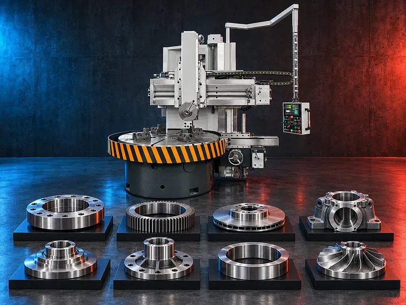
Vertical turning concept
The workpiece is clamped to a horizontal rotating table and the cutting tool moves along the supported vertical and horizontal directions. The component rotates while the tool removes material from the required surfaces.
The practical result depends on table geometry spindle and drive condition crossrail and ram rigidity workholding balance tool setup cutting data thermal control and inspection.
Potential turning operations
Potential operations include external and internal cylindrical turning facing boring shoulders steps grooves recesses chamfers and selected profiles when supported by the toolhead travel and tooling.
Taper turning may use toolhead swivel programmed manual coordination or another method according to the verified design. Threading drilling milling or special features should not be assumed without model evidence.
Roughing and finishing
Rough machining removes the planned stock with cutting conditions that remain within machine workpiece tool and workholding limits. Finishing passes target final dimensions geometry and surface quality.
The sequence should manage stock distribution casting skin interrupted cuts hardness variation heat tool wear deflection and inspection allowance.
Suitable components and applications
Potential workpieces include rings flanges discs wheels pulleys housings covers valve bodies large bearings gear blanks and other wide or heavy rotational components within the verified envelope.
Potential applications include general engineering energy pumps valves gear production heavy maintenance and other sectors after technical review. Suitability cannot be claimed for every industry or part.
Single column and double column arrangements
Vertical lathes may use single column open side construction or double column portal construction according to the required envelope and machine design. Each arrangement affects access rigidity crossrail support and loading space.
The number of rams side heads toolposts and stations is model specific and must be confirmed from approved documentation.
Rotating table and main drive
The table supports clamps and rotates the workpiece through the main drive. Table diameter load permitted speed torque bearing condition and balance limits are central to machine selection.
Large irregular or offset parts may create unbalanced forces even when total weight is within the nominal load. The approved clamping and balancing procedure must be followed.
Crossrail ram and toolhead movement
The crossrail positions the toolhead for workpiece height while the ram and saddle provide cutting movement according to the machine design. Locks gibs guideways screws feeds and geometry influence rigidity and accuracy.
Ram extension and tool overhang should be controlled because increased reach can raise deflection vibration and collision risk.
Workholding and setup
Workholding may use table jaws T slot clamps stops fixtures locating rings supports and custom arrangements selected for the part geometry cutting force table load and datum plan.
The setup should control radial and axial location lifting sliding distortion and unbalance while maintaining tool clearance chip flow inspection access and safe removal.
Tooling and cutting data
Potential tooling includes turning boring grooving chamfering facing and form tools with holders interfaces and inserts compatible with the toolhead and duty.
Cutting speed feed depth of cut tool geometry grade coolant and pass sequence should suit the material hardness interrupted surfaces machine rigidity available power stock allowance finish and tooling supplier guidance.
Chip and coolant management
Large turning operations can produce long heavy hot or sharp chips. Guards chip deflectors hooks conveyors or collection methods should be selected according to the machine and process.
Suitable cutting fluid may support heat control lubrication chip evacuation tool life and finish. Fluid delivery filtration concentration maintenance and safe handling require process and site review.
Accuracy and inspection
Acceptance may include diameters bores lengths face flatness parallelism perpendicularity concentricity runout taper groove dimensions shoulder locations and surface finish according to the drawing.
Finished accuracy depends on table and spindle geometry crossrail and ram alignment guide condition backlash thermal behavior workholding tool deflection cutting data datum strategy and calibrated inspection equipment.
How to choose the correct machine
Provide the component drawing material hardness outside and inside diameters height weight center of gravity features stock allowance tolerances finish quantities batch size lifting constraints and target output.
Selection should consider table diameter and load maximum turning diameter and height swing under rail ram travels crossrail movement spindle speed and torque power feeds tool interface side head options coolant chip management DRO utilities foundation and service access.
Technical information to verify
The approved exact model source must confirm manufacturer brand model construction table diameter table load maximum turning diameter maximum workpiece height spindle speed range torque power crossrail travel ram travels feeds and toolhead swivel.
It must also confirm accuracy test standard DRO or controls guideway type lubrication coolant electrical supply dimensions weight foundation lifting points included tooling guards safety devices and optional equipment.
Loading lifting and site handling
Heavy components require an approved lifting plan covering crane or hoist capacity certified lifting points slings spreaders center of gravity travel path table protection and communication between personnel.
No workpiece should be loaded from estimated weight alone. Part weight fixture weight table capacity balance and dynamic limits must be verified before rotation.
Safety requirements
The risk assessment should address rotating large workpieces protruding clamps entanglement ejected parts tool breakage heavy and hot chips table and crossrail movement crush zones lifting coolant noise and electrical hazards.
Perimeter guarding emergency stops secure clamping balance checks safe speed restricted zones operating instructions training personal protective equipment isolation and maintenance controls must follow approved documentation and site requirements.
Installation maintenance and support
Site planning should cover foundation design floor capacity anchoring leveling lifting route crane coverage electrical supply grounding coolant chip handling lighting ventilation operator platforms inspection space and maintenance access.
Preventive maintenance should cover lubrication table bearings main drive guideways screws nuts gibs crossrail locks rams feeds hydraulic equipment coolant electrical controls guards geometry and alignment. Supply scope training spare parts warranty and service commitments require approved confirmation.
Limitations and alternative processes
A conventional vertical lathe is not automatically suitable for every material diameter height weight geometry tolerance finish duty cycle or productivity target. Very tall slender eccentric unbalanced or complex parts may require another solution.
A horizontal lathe floor boring machine CNC vertical turning lathe vertical turning center mill turn machine or another process may be more suitable depending on the component and production requirement.
Technical review and next step
Send the component drawing with material hardness dimensions weight center of gravity features stock allowance tolerances finish quantities fixture and lifting concept current process utilities and target output.
SAKKARY MACHINERY will review machine envelope table load workholding balance tooling cutting sequence inspection lifting utilities safety alternatives and information that still requires manufacturer verification.
Questions we are asked
What is a conventional vertical lathe?
It is a manually controlled turning machine that supports and rotates the workpiece on a horizontal table while cutting tools approach from vertical or horizontal directions provided by the machine.
Which parts are suitable for vertical turning?
Potential parts include rings flanges discs wheels housings valve bodies gear blanks and other wide or heavy rotational components within verified machine and workholding limits.
Which operations can it perform?
Potential operations include external and internal turning facing boring tapers grooves shoulders steps and rough or finish machining when supported by the exact configuration.
Why use a vertical lathe for heavy parts?
The horizontal table can support wide heavy components during loading and rotation but suitability still depends on verified table load balance diameter height and lifting arrangements.
Can it machine every large component?
No. Material geometry weight balance tolerance finish duty cycle tooling and machine envelope must be reviewed for each part.
What information is required for selection?
Provide the drawing material hardness diameters height weight center of gravity features tolerances finish quantities lifting constraints and target output.
Tell us the part you need to make
An engineer reads every request. Usually the same working day.
Related
- Heavy-Duty Gap-Bed Conventional Lathes Heavy-duty conventional lathes for turning large-diameter, long, and heavy rotational components. The gap-bed design provides additional swing near the headstock for suitable short workpieces.
- Gantry Type Milling Machine A gantry-type milling machine provides an open working area for machining suitable large or heavy components. Selection depends on workpiece dimensions, weight, material, required operations, tolerances, finish, and production requirements.
- Boring Machine for Workshop Machining A boring machine for drilling, enlarging, finishing, and aligning suitable holes in individual parts and small production batches. The correct model depends on workpiece size, material, hole diameter, depth, tolerance, surface finish, setup, tooling, and required output.