

COMPACT WORKSHOP MACHINES
Compact Milling Drilling Machines
Compact machines that combine suitable milling and drilling operations in one workshop footprint for small components, prototypes, repair work, training, and light production. The correct model depends on workpiece size, material, table movement, spindle, tooling, tolerance, finish, duty pattern, and available space.
A compact milling drilling machine combines a vertical spindle, drilling quill, and movable worktable so the operator can perform supported drilling and milling tasks without transferring the component between separate machines. Exact construction varies between bench, stand mounted, geared head, belt driven, manual feed, power feed, and digitally assisted models. Compact size does not mean that every small part is suitable. Machine rigidity, table area, axis travels, spindle taper, quill travel, power, tooling, workholding, duty cycle, chip control, and required accuracy must be checked for the exact application and model.
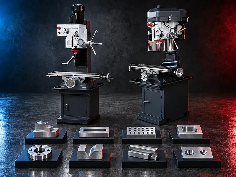
Combined milling and drilling concept
The vertical spindle rotates drills, end mills, and other compatible tools while the table positions the workpiece along the supported axes. The quill may provide short vertical movement for drilling and selected light machining tasks.
The exact machine architecture, column, head movement, table travels, quill functions, feed system, and control or display options are model specific.
Potential drilling operations
Potential operations include center drilling, drilling, reaming, counterboring, countersinking, spot facing, and selected tapping or light boring when supported by the verified spindle, feeds, tooling, and machine rigidity.
Each hole should be reviewed for material, starting condition, diameter, depth, tolerance, finish, tool interface, speed, feed, coolant, chip evacuation, and inspection.
Potential milling operations
Potential operations include light face milling, end milling, slotting, keyway cutting, shoulders, steps, shallow pockets, and selected angular work when supported by the head, table, tooling, and setup.
Cutting width, depth, tool engagement, overhang, workholding, chip clearance, spindle load, table feed, tolerance, and finish must remain within the verified machine limits.
Suitable workpieces and applications
Potential workpieces include small brackets, plates, blocks, fixtures, tooling parts, model components, repair parts, instrument components, maintenance items, and other parts within the verified table and travel envelope.
Potential applications include maintenance workshops, training centers, toolrooms, prototype development, educational laboratories, small engineering businesses, individual parts, and light small batch work.
Compact footprint and workshop planning
A compact machine may reduce required floor area and place drilling and milling functions at one station. This may suit workshops with limited space or varied low volume tasks.
The full installation still needs room for the stand or bench, operator access, table movement, tooling, workpiece handling, guards, electrical supply, coolant or chip trays, cleaning, and maintenance.
Machine structure and rigidity
The column, base, head, table, saddle, guides, spindle, and drive determine the structural response to cutting loads. A heavier or larger appearance does not by itself prove rigidity, capacity, or accuracy.
Foundation or bench stiffness, mounting, leveling, guide adjustment, lubrication, spindle condition, head locking, table locks, workholding, tool overhang, and cutting data affect the result.
Table movement and setup
The worktable normally provides longitudinal and cross positioning, while vertical positioning may come from the head, column, knee, or another arrangement depending on the verified model.
Setup should control table travel, load, overhang, backlash, axis locks, cutter access, spindle clearance, workpiece height, datum transfer, collision risk, chip flow, and inspection access.
Spindle head and quill
The vertical spindle carries compatible drills, milling cutters, holders, chucks, collets, and adapters. The quill may provide manual or powered feed according to the verified machine.
Spindle taper, speed range, motor power, torque, quill travel, quill diameter, feed range, head tilt, head elevation, depth stops, tapping functions, and braking require model verification.
Tooling and workholding
Potential tooling includes drill chucks, collets, end mill holders, end mills, face mills, slot drills, drills, reamers, countersinks, counterbores, tapping tools, boring heads, and adapters compatible with the spindle and duty.
Workholding may include compact vises, clamps, parallels, angle plates, rotary tables, fixtures, and supports selected for the component geometry, datum plan, cutting force, table load, and inspection method.
Speeds feeds and cutting strategy
Spindle speed, feed, depth of cut, width of cut, tool engagement, coolant, and pass sequence should suit the material, tool, machine rigidity, available power, finish, and tool supplier recommendations.
Compact machines may require lighter cuts and controlled tool overhang. Excessive load, weak workholding, poor head locking, or trapped chips can reduce tool life, finish, accuracy, and safety.
Digital readout and control options
Depending on the verified model, position may be read from handwheel dials, digital scales, a digital readout, or another control arrangement. Powered table feed or speed display may also be available on selected versions.
Display resolution does not equal machining accuracy. Mechanical geometry, backlash, scale installation, datum setting, tool deflection, thermal effects, setup, and inspection remain important.
Accuracy and inspection
The acceptance plan may include hole diameter and position, depth, flatness, straightness, parallelism, perpendicularity, slot width and depth, pocket dimensions, angular features, surface finish, and fit with mating parts.
Finished quality depends on machine geometry, guide condition, backlash, spindle runout, head alignment, thermal behavior, workholding, tool condition, cutting data, datum strategy, and calibrated inspection equipment.
How to choose the correct machine
Provide component drawings with material, hardness, dimensions, weight, hole data, milling features, machining envelope, tolerances, finish, quantities, batch sizes, setup constraints, duty pattern, and target output.
Selection should also consider table dimensions and load, longitudinal cross and vertical travels, spindle taper, speed range, quill travel, feeds, motor power, head movement, drilling and milling capacity, DRO, power feed, coolant, tooling, stand, and floor space.
Technical information to verify
The approved exact model source must confirm the manufacturer, brand, model, machine type, drilling capacity by material and test condition, milling capacity, table dimensions, table load, longitudinal travel, cross travel, vertical travel, spindle taper, speed range, quill travel, feeds, and motor power.
It must also confirm head tilt or movement, distance from spindle to table and column, DRO or display, power feed, positioning accuracy, repeatability, guideway type, lubrication, coolant, electrical supply, dimensions, weight, stand, foundation or mounting, included accessories, guards, and safety devices.
Coolant chips and maintenance
Suitable coolant may control heat, lubricate the cut, support tool life, and carry chips when required by the material and tooling. Chips should be controlled around the cutter, workpiece, vise, table, T slots, column, guards, and electrical components.
Preventive maintenance should cover lubrication, spindle and quill, belts or gears, feeds, screws, nuts, gibs, guides, head locks, table locks, coolant, electrical controls, guards, and periodic alignment checks.
Safety requirements
The risk assessment should address rotating tools and spindles, entanglement, sharp and hot chips, tool breakage, ejected workpieces, loose chuck keys, clamping, axis movement, pinch points, coolant, manual handling, and electrical hazards.
The exact guards, emergency stops, spindle and tool checks, chuck key control, workholding procedures, safe setup zones, operating instructions, training, personal protective equipment, and maintenance controls must follow approved documentation and site requirements.
Installation and lifecycle support
Site planning should cover machine and stand footprint, bench or foundation stiffness, leveling, lifting access, electrical supply, grounding, coolant, lubrication, chip collection, lighting, ventilation, tooling storage, inspection space, maintenance access, and operator training.
The exact supply scope, commissioning, training, preventive maintenance, spindle guide and drive service, consumables, spare parts, warranty, and service commitments require confirmation in the approved technical and commercial offer.
Limitations and alternative processes
A compact milling drilling machine is not automatically suitable for every workpiece, material, size, weight, geometry, tolerance, finish, duty cycle, batch volume, or productivity target.
A bench drill, column drill, turret mill, knee mill, bed type mill, CNC machining center, boring machine, or another process may be more suitable for larger components, heavier cuts, complex geometry, tighter tolerances, automation, or higher volume.
Technical review and next step
Send the component drawings with material, hardness, dimensions, weight, hole and milling features, tolerances, finish, quantities, setup constraints, available tooling, duty pattern, and target output.
SAKKARY MACHINERY will review the machining envelope, table and spindle requirements, tools, workholding, process sequence, inspection, utilities, safety needs, alternative processes, and information that still requires manufacturer verification.
Questions we are asked
What is a compact milling drilling machine?
It is a workshop machine that combines supported vertical drilling and light milling functions in a compact table and spindle arrangement.
Which operations can it perform?
Potential operations include drilling reaming countersinking counterboring light face and end milling slots keyways shoulders steps and shallow pockets when supported by the model and setup.
Which workpieces are suitable?
Potential workpieces include small brackets plates blocks fixtures tooling model parts repair parts and maintenance components within the verified table travels load and spindle reach.
Is a compact machine suitable for heavy milling?
Not automatically. Compact machines may require lighter cuts and can be limited by rigidity power travels table load spindle and duty cycle.
Can it replace a full size mill or CNC machining center?
Not automatically. Larger or CNC machines may be better for heavy cuts complex geometry tight repeatability automation larger parts or higher production volume.
What information is required for selection?
Provide drawings material hardness dimensions weight hole and milling features tolerances finish quantities duty pattern setup constraints and target output
Tell us the part you need to make
An engineer reads every request. Usually the same working day.
Related
- Heavy-Duty Gap-Bed Conventional Lathes Heavy-duty conventional lathes for turning large-diameter, long, and heavy rotational components. The gap-bed design provides additional swing near the headstock for suitable short workpieces.
- Gantry Type Milling Machine A gantry-type milling machine provides an open working area for machining suitable large or heavy components. Selection depends on workpiece dimensions, weight, material, required operations, tolerances, finish, and production requirements.
- Boring Machine for Workshop Machining A boring machine for drilling, enlarging, finishing, and aligning suitable holes in individual parts and small production batches. The correct model depends on workpiece size, material, hole diameter, depth, tolerance, surface finish, setup, tooling, and required output.