

AUTOMATIC TUBE CUTTING
Automatic Tube Cutting Saws
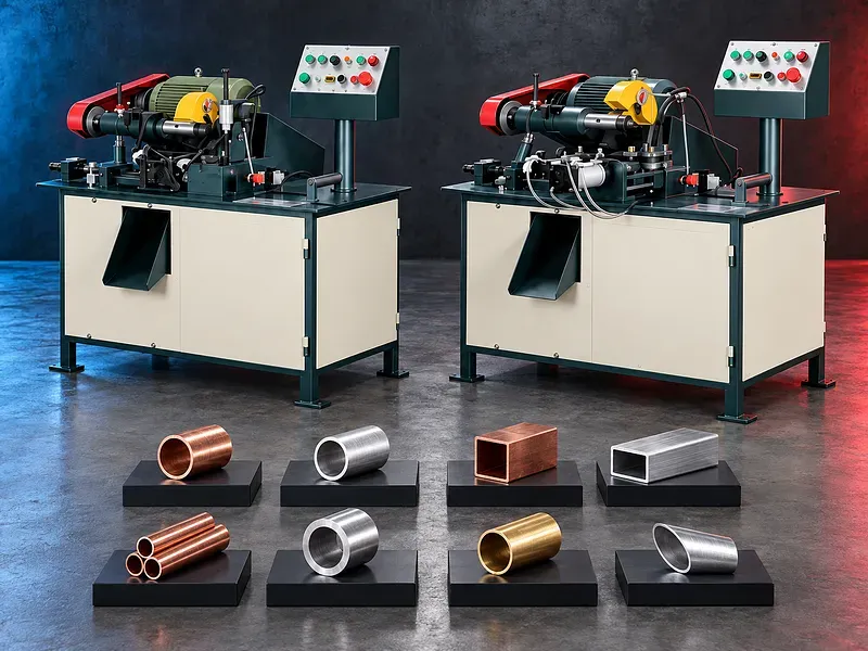
Automatic tube cutting saws feed clamp and cut supported metal tubes into controlled lengths for repeat production. The pictured machines are presented for copper and aluminum applications but material compatibility cutting range blade data accuracy and output must be verified from the approved catalog for the exact model.
An automatic tube cutting saw coordinates material feeding length positioning clamping blade movement cutting separation and part discharge according to the machine configuration. The process can reduce repeated manual measuring and support consistent batches when the tube blade tooling settings and inspection method are correctly matched. The uploaded image visibly labels two machines as JB T32D and JB T50D and includes a specification table. Those values are not treated as approved technical evidence. Selection requires the current manufacturer datasheet together with tube material profile outside dimensions wall thickness length tolerance cut quality batch size bar length loading method and downstream process.
Automatic cutting cycle
A typical cycle loads or presents the tube advances it to the programmed or stopped length clamps it securely moves the rotating saw blade through the section returns the blade releases the part and prepares for the next feed.
The exact sequence sensors stops feed mechanism and discharge arrangement are model specific. A validated cycle still requires operator supervision and inspection.
Potential tube materials
The uploaded artwork presents the machines for copper and aluminum. Exact supported grades tempers wall thicknesses and profiles require verification because material strength ductility heat generation chip behavior and surface sensitivity affect cutting.
Other metals should not be assumed compatible without approved capacity blade and process data.
Tube profiles and starting stock
Potential workpieces may include supported round tubes and other profiles only when the clamping feed and blade arrangement are designed for them.
Outside dimensions wall thickness straightness ovality seam condition surface coating bar length bundle condition and end quality should be provided for selection.
Material feeding and length control
The feed system may use a mechanical stop pneumatic or hydraulic gripper servo movement rollers or another arrangement according to the model. It should advance the tube without slipping marking or losing the datum.
Programmed feed distance or display resolution does not by itself prove finished length accuracy. Backlash gripping cut width tube movement temperature and measurement method affect the result.
Clamping and support
The tube should be clamped close enough to the cut to resist blade force without crushing thin walls or damaging sensitive surfaces. Jaws bushes guides or supports should match the section.
Long stock may require infeed stands straightening guides bundle loading or other support. Cut parts may need controlled discharge to prevent denting mixing or operator exposure.
Saw blade selection
Blade diameter bore thickness tooth count tooth geometry material coating and permitted speed should match the machine tube material diameter wall thickness cut quality and production duty.
The blade information visible in the image requires verification from the approved manual. Incorrect blade selection can cause burrs chatter heat distortion tooth damage kickback or unsafe operation.
Cutting speed and feed
Blade speed and feed rate should suit the material section wall thickness blade tooth engagement coolant or lubricant and required finish. Thin walls and small contact sections need controlled tooth engagement.
Excessive feed can deform the tube overload the blade or increase burrs while insufficient feed can rub generate heat and shorten blade life.
Lubrication and chip control
Suitable lubrication or minimum quantity delivery may reduce friction heat built up edge and blade wear when permitted by the application. Dry cutting suitability depends on verified blade and machine data.
Chips should be controlled around the blade guard clamps feed guides collection chute and electrical components. Copper and aluminum chips should be separated where material recovery requires it.
Cut length and end quality
Acceptance may include cut length squareness burr height edge rollover surface marks deformation ovality and absence of cracks or blade steps according to the drawing.
Some downstream processes may require deburring chamfering washing or end facing. The saw should be evaluated as one step in the complete production route.
Automatic production and counters
Depending on the verified control the operator may set length quantity feed speed cutting speed or cycle count and monitor alarms or production totals.
Stored settings should be protected and linked to a verified part setup. Automatic counting does not replace first piece approval periodic measurement and tool condition checks.
Workpiece handling and collection
The layout should provide safe loading of raw tubes and controlled removal of cut pieces scrap ends and chips. Chutes bins conveyors or part trays may be required according to length and surface sensitivity.
Short pieces can bounce or jam while long tubes can swing or create leverage. Handling arrangements should be included in the risk assessment.
Quality inspection
The quality plan should define material identity initial datum cut length tolerance squareness burr criteria surface condition sample frequency first piece approval calibrated instruments and nonconforming part control.
Measurement should allow the part to cool or stabilize where temperature can affect tolerance. Gauge method and contact pressure should suit soft tube materials.
How to choose the correct machine
Provide tube material grade and temper profile outside dimensions wall thickness starting length required cut lengths tolerances end quality quantities batch size loading method available utilities and target output.
Selection should consider supported material range minimum and maximum section blade system spindle power and speed feed mechanism length control clamping cycle rate lubrication chip collection loading discharge control functions floor space and service access.
Technical information to verify
The approved exact model source must confirm manufacturer brand model supported materials profile range minimum and maximum cutting dimensions wall thickness conditions blade diameter bore thickness tooth specification spindle speed motor power feed range cut length range and accuracy test basis.
It must also confirm clamping method feed mechanism control functions coolant or lubrication electrical supply air requirements dimensions weight loading support discharge accessories guards safety devices cycle times and included options.
Productivity and production flow
Actual output depends on stock loading feed length cut cycle blade condition chip clearing part discharge inspection deburring tool change material change and downtime rather than the stated cuts per minute alone.
A realistic study should use the actual tube grade dimensions cut length batch quantity tolerance and downstream handling.
Safety requirements
The risk assessment should address the rotating saw blade cutting zone automatic feed moving clamps ejected pieces sharp chips long stock movement pinch points noise lubricants and electrical hazards.
Blade guards interlocks emergency stops secure clamping stock supports safe loading zones isolation operating instructions training personal protective equipment and maintenance controls must follow approved documentation and site requirements.
Installation maintenance and support
Site planning should cover floor capacity leveling anchoring or stable feet electrical supply grounding compressed air if required lubrication ventilation lighting raw tube support part collection chip bins blade storage operator access and maintenance clearance.
Preventive maintenance should cover spindle bearings belts or drives blade flange guards feed mechanism clamps guides sensors lubrication controls electrical equipment fasteners and alignment. Supply scope training blades spare parts warranty and service commitments require approved confirmation.
Limitations and alternative processes
An automatic tube cutting saw is not automatically suitable for every material profile diameter wall thickness length tolerance finish batch volume or output target.
A circular cold saw band saw abrasive saw laser tube cutter sawing center lathe cutoff operation or another process may be more suitable for larger sections harder materials complex profiles angled cuts tighter burr control or flexible production.
Technical review and next step
Send tube drawings and samples with material grade profile outside dimensions wall thickness starting length cut lengths tolerances end quality quantities handling method utilities and target output.
SAKKARY MACHINERY will review process fit model range blade system feeding clamping cut quality inspection handling safety alternatives and information that still requires manufacturer verification.
Questions we are asked
What is an automatic tube cutting saw?
It is a sawing machine that coordinates tube feeding length positioning clamping cutting return and part release for supported repeat production.
Can it cut copper and aluminum tubes?
The uploaded artwork presents copper and aluminum applications but the exact grades profiles diameters wall thicknesses and blades require approved model verification.
Which models are shown in the image?
The uploaded image visibly labels the machines JB T32D and JB T50D. Their technical specifications remain subject to verification from current official documentation.
Does programmed length equal finished cut accuracy?
No. Clamping feed movement blade width backlash temperature tube condition and measurement method also affect the final length.
How should the saw blade be selected?
Select blade diameter bore thickness teeth geometry material coating and speed from approved machine and blade guidance for the tube material dimensions and duty.
What information is required for selection?
Provide tube material grade profile outside dimensions wall thickness starting length cut lengths tolerances end quality quantities handling method utilities and target output.
Tell us the part you need to make
An engineer reads every request. Usually the same working day.
Related
- Heavy-Duty Gap-Bed Conventional Lathes Heavy-duty conventional lathes for turning large-diameter, long, and heavy rotational components. The gap-bed design provides additional swing near the headstock for suitable short workpieces.
- Gantry Type Milling Machine A gantry-type milling machine provides an open working area for machining suitable large or heavy components. Selection depends on workpiece dimensions, weight, material, required operations, tolerances, finish, and production requirements.
- Boring Machine for Workshop Machining A boring machine for drilling, enlarging, finishing, and aligning suitable holes in individual parts and small production batches. The correct model depends on workpiece size, material, hole diameter, depth, tolerance, surface finish, setup, tooling, and required output.