

HOT FORGING PRODUCTION SOLUTIONS
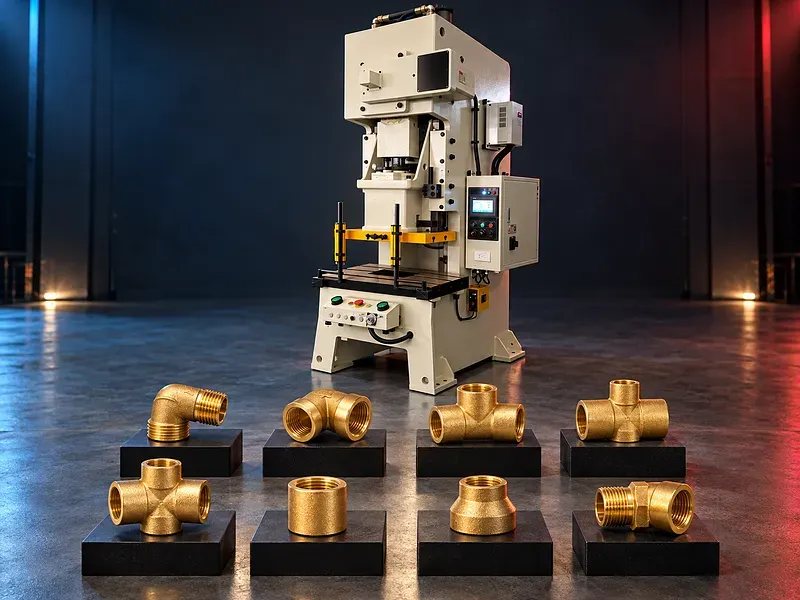
Automatic Hot Forging Press for Brass Valve and Tee Production
An automatic hot forging press can form heated compatible metal blanks into near net shapes for selected valve bodies fittings and refrigeration tees when the press tooling heating method and automation are engineered for the exact part. Selection requires verified alloy billet die force energy temperature cycle quality utility and safety data.
The production cell may combine billet preparation controlled heating automatic transfer die lubrication forging ejection flash handling cooling and inspection. Additional trimming shot blasting machining threading cleaning and leak testing may still be required according to the finished component. The phrase pneumatic stamping does not define the press mechanism. Pneumatic equipment may operate a clutch control system ejector transfer device or another auxiliary function. The exact drive principle and every performance claim must be confirmed from the approved machine datasheet and process trial.
What the production solution does
The solution is intended to place a heated compatible blank in a matched die and apply controlled force and energy so the material flows into the required cavity. The objective is a repeatable forging that provides suitable material distribution for the next manufacturing stages.
Part geometry alloy temperature billet volume lubrication die condition press motion and transfer timing interact. A technically suitable solution can only be selected after the exact part and process have been reviewed.
Proposed brass valve and refrigeration tee application
The requested application refers to valve parts and refrigeration tee components made from brass. This intended use requires confirmation against the exact alloy part drawing forging drawing finished drawing pressure duty and applicable product requirements.
A material described only as brass is not enough for process approval. Chemical composition hot workability grain behavior cracking risk dezincification requirements and traceability may differ between grades.
Billet and blank preparation
Production normally starts with approved bar or preform material that is cut or prepared to a controlled mass and geometry. Billet volume influences cavity filling flash formation load and final material distribution.
The approved process should define alloy source diameter cut length mass tolerance end condition cleanliness identification storage sampling and rejection criteria. Cutting method and any surface preparation must also be confirmed.
Controlled heating
The blank must be heated within a validated process window before forging. Heating that is too low may restrict material flow and increase load while excessive or uneven heating may affect surface condition grain structure dimensions or die life.
Heating technology temperature range soak or residence time temperature uniformity measurement location sensor type calibration rejected blank handling energy demand extraction and fire controls require exact confirmation.
Automatic blank transfer
An automatic feeder robot manipulator or transfer system may move the heated blank from the heater to the die when the selected cell supports this function. Transfer time and gripping must preserve temperature and place the blank correctly without damaging its surface.
The handling study should confirm blank orientation gripping area permissible temperature loss motion path cycle interlocks missed pick detection dropped part containment and safe recovery procedures.
Forging die and forming stages
The die set controls material flow and creates the intended preform or finished forging geometry. A process may use one or more stages such as upsetting preforming blocking and finishing according to the component and available equipment.
Die material heat treatment cavity design draft fillets parting line flash land vents inserts guidance alignment cooling lubrication expected wear repair method and ownership must be approved by the responsible tooling specialist.
Press force energy and motion
Successful forging depends on more than nominal press force. The machine must supply the required load and energy through the relevant part of its motion while keeping the frame slide guides bed and tooling within approved limits.
The process calculation should cover projected area flow stress temperature friction forming stages flash load energy per stroke rated point stroke speed contact time eccentric load and an approved engineering margin.
Drive clutch and pneumatic functions
The press may use a mechanical hydraulic servo or another verified drive arrangement. An air system may support clutch operation balancing ejection gripping valves or controls depending on the selected design.
The approved datasheet must identify the drive principle clutch and brake arrangement air pressure and consumption valve monitoring stopping performance response time reservoir treatment and behavior after pressure loss.
Die lubrication and cooling
Forging lubrication may support material flow release surface condition and die protection. The lubricant formulation quantity spray location timing carrier medium and extraction must suit the alloy die and process.
Tool temperature and cooling should be controlled within a validated range. Excess lubricant or cooling may create thermal shock smoke contamination fire risk unstable dimensions or defects.
Part ejection flash and hot material handling
After forming the component must be released from the die and transferred safely to the next stage. Flash runners scale rejected blanks and hot parts need defined routes that do not interfere with tooling sensors operators or production flow.
Confirm ejector type stroke force timing sensors chute conveyor container heat resistance guarding jam detection and safe clearing method. Flash trimming may require separate tooling and equipment unless an approved integrated process is supplied.
Downstream operations
A forging is not automatically a finished valve body or refrigeration tee. Depending on the approved product route it may require trimming cooling heat treatment cleaning shot blasting machining drilling boring threading deburring washing marking assembly and pressure or leak testing.
The page should not promise a complete finished product until each downstream operation inspection standard and interface has been defined.
Quality and process control
Inspection may include billet mass temperature transfer time forging fill flash dimensions surface laps folds cracks scale parting line mismatch grain flow hardness and machining allowance according to the approved control plan.
Finished pressure containing components may need additional dimensional material surface cleanliness pressure leakage and traceability checks. Acceptance criteria and test methods must follow the applicable drawing and standard.
Automation controls and traceability
The control system may coordinate heating readiness blank feed transfer die lubrication press cycle ejection cooling alarms and rejected part routing when these functions are included in the approved scope.
Required records may include material batch billet temperature cycle status alarm reason tool identity quantities scrap inspection and operator action. Control architecture interfaces data retention and access permissions require confirmation.
Safety and operating risks
Risks include hot metal crushing entrapment unexpected slide movement ejected material die failure fire fumes lubricant spray noise high pressure fluids compressed air electrical energy and manual intervention during jams or maintenance.
The cell requires a documented risk assessment with approved guards interlocks emergency stops safe modes isolation procedures die blocks hot material controls extraction fire protection personal protection training inspection and supervised recovery methods.
Installation and commissioning
Site preparation should cover delivery access foundation floor loading anchoring electrical supply compressed air cooling water extraction heating utilities fire controls material storage die handling hot part flow scrap route and maintenance access.
Commissioning should verify geometry lubrication drive systems stopping performance safety functions heater control transfer timing die alignment temperature window sample forgings inspection training documents and an agreed acceptance trial.
Maintenance and lifecycle support
Preventive maintenance should follow approved schedules for the drive clutch brake bearings guides lubrication heater transfer devices grippers ejectors sensors valves cooling extraction guards and safety controls.
The final scope should define recommended spares die maintenance consumables lubricants calibration tools software backups technical documents training response process and responsibilities for the press heater automation and tooling.
Information required for selection
Provide the finished part drawing forging drawing sample or model alloy standard billet dimensions and mass annual and batch quantities target cycle downstream operations tolerances surface requirements traceability and applicable valve or refrigeration standards.
Also provide die concept forming stages calculated force and energy heating method and temperature window required automation utilities site layout shift pattern operator access maintenance capability safety requirements and acceptance criteria.
Technical information to verify
Approved documents must confirm press type nominal force rated point force curve energy curve stroke speed shut height adjustment bed and slide dimensions die weight eccentric load guides drive motor clutch brake stopping data lubrication controls operating modes automation interfaces and cycle limitations.
Heater type temperature range heating capacity transfer system ejector air demand electrical load cooling demand extraction dimensions weight foundation guarding safety functions noise basis standard equipment options documents training warranty service and acceptance method also require verification.
Limitations and publishing status
The supplied title does not verify that one machine can produce every brass valve or refrigeration tee. It does not verify the press drive the pneumatic function force temperature speed automation tooling output quality standard or finished product route.
Publication requires the exact approved machine datasheet process and forging drawings alloy standard heater and automation scope tooling proposal safety documentation acceptance plan approved image technical review staging review and final content approval.
Technical review and next step
Send the part and forging drawings alloy billet data output target process stages utility information and site layout for engineering review. Samples and the required finished part tests should be included where available.
The review should define the suitable press and heater tooling sequence automation inspection downstream equipment safety concept acceptance trial installation training maintenance and spare parts scope.
Questions we are asked
What does an automatic hot forging press do?
It forms a heated compatible blank inside a die using controlled force and energy. The press must be selected from the exact part alloy tooling temperature and production requirements.
Can it produce brass valve bodies and refrigeration tees?
It may be suitable for selected parts after the alloy drawings forging stages press capacity tooling heating automation and quality requirements are technically approved.
Does pneumatic stamping describe the main press drive?
Not necessarily. Pneumatic systems may operate a clutch control ejector gripper or another auxiliary function. The approved datasheet must identify the actual drive principle.
Is the forging ready for assembly after pressing?
Not always. Trimming cleaning machining threading washing marking assembly and pressure or leak testing may be required according to the product route.
What information is needed for machine selection?
Provide part and forging drawings alloy and billet data process stages force and energy calculations heating window tooling automation output target utilities site layout safety needs and acceptance criteria.
Tell us the part you need to make
An engineer reads every request. Usually the same working day.
Related
- Heavy-Duty Gap-Bed Conventional Lathes Heavy-duty conventional lathes for turning large-diameter, long, and heavy rotational components. The gap-bed design provides additional swing near the headstock for suitable short workpieces.
- Gantry Type Milling Machine A gantry-type milling machine provides an open working area for machining suitable large or heavy components. Selection depends on workpiece dimensions, weight, material, required operations, tolerances, finish, and production requirements.
- Boring Machine for Workshop Machining A boring machine for drilling, enlarging, finishing, and aligning suitable holes in individual parts and small production batches. The correct model depends on workpiece size, material, hole diameter, depth, tolerance, surface finish, setup, tooling, and required output.