

RECTANGULAR DUCT CORNER PRODUCTION
Duct Corner Punching Machine for HVAC Fabrication
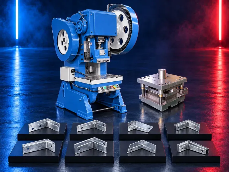
A duct corner punching machine uses a matched press and die to produce corner pieces or corner features for rectangular HVAC ducts. Correct selection depends on the required corner drawing material thickness die design press capacity production volume and downstream assembly method.
The machine converts prepared sheet or strip into repeatable duct corner components through a controlled pressing cycle. Depending on the approved tooling the operation may include punching cutting blanking or light forming. A wide working area and accessible die setting can simplify material handling and tool changes when the press layout matches the intended corner product. The die remains the key element that defines geometry clearance and finished quality. Claims for production rate press force thickness range angle steel processing bending or stretching require confirmation from the exact machine data sheet approved dies and representative trials.
What the machine does
The machine applies a controlled press stroke through a dedicated die to create a duct corner part or a specified corner feature. The finished component is then used during rectangular duct flange assembly.
Machine suitability depends on the actual part drawing rather than the general description of the press.
Corner component and drawing
Provide the approved corner drawing with dimensions hole pattern bends radii material direction and allowable tolerances. Different flange systems and assembly methods can require different corner geometry.
Confirm how the corner engages the flange and whether the completed duct needs fasteners sealant or an additional closing operation.
Press and die relationship
The press supplies motion and force while the die controls cutting clearance location and form. A machine cannot be approved for a corner product until the required die and press capacity have been checked together.
Verify die dimensions shut height mounting pattern feed direction ejection method tool weight and safe handling procedure.
Processing cycle
The operator or feeding system positions the stock against an approved reference before the press completes the cycle. The part and scrap must leave the die without creating a jam or exposing the operator to the working zone.
Confirm loading positioning stroke return ejection collection and inspection stages for the intended production method.
Materials and thickness
Submit the material grade coating thickness hardness and surface finish with the part drawing. Galvanized sheet stainless steel aluminium and other materials require separate force clearance wear and sample confirmation.
Do not generalize a thickness range from one material or die to another.
Press capacity and working area
Required capacity depends on cutting perimeter material shear strength forming work number of simultaneous features and die design. Adequate working area daylight stroke and bolster size are also necessary.
Confirm the calculation and a suitable operating margin through approved engineering data before production use.
Die access and changeover
Accessible tooling and a movable or removable bolster can support die setting cleaning and changeover when included in the verified configuration. Heavy dies may require a lifting device transfer cart or fixed handling procedure.
Record alignment method fasteners setup values trial piece approval and tool storage requirements for every die.
Quality control
Inspect dimensions hole location edge condition burr height flatness formed angles cracks coating damage and fit with the matching duct flange. Acceptance must follow the approved drawing and assembly test.
Check the first part after setup material change die service adjustment or extended stoppage and continue at an approved sampling frequency.
Integration in duct production
Corner production should be coordinated with sheet cutting beading notching flange forming folding lock forming seam closing corner fitting sealing and final inspection.
Match corner quantities and packaging to duct orders so the assembly station receives the correct part without mixing sizes or flange systems.
Productivity and material use
Accepted output depends on part layout feed method stroke cycle operator work die condition scrap removal inspection and the capacity of surrounding processes.
Measure accepted corners per shift and actual material yield during representative production trials instead of relying on general speed claims.
Additional operations
Some press and die combinations may also punch cut blank bend or lightly form other sheet components. Processing angle sections or performing broader press work requires dedicated tooling capacity checks guarding and written approval.
Treat every additional application as a separate engineering case with its own material drawing die and acceptance trial.
Common process risks
Incorrect clearance worn cutting edges poor alignment unstable stock feed trapped scrap or insufficient capacity can cause burrs distortion cracks incomplete cuts rapid tool wear or jams.
Stop production when parts fall outside the drawing or when the die press guarding or ejection system shows abnormal behavior.
Safety and operator protection
The working area includes moving press components pinch and crush points sharp stock finished edges ejected scrap and stored mechanical or pneumatic energy. Guards interlocks emergency stops control reliability and safe access must follow the approved risk assessment.
Procedures must cover loading die setting trial strokes jam recovery scrap removal tool handling isolation and maintenance. Hand access to the danger zone during an enabled cycle is not acceptable.
Installation and site readiness
Confirm floor capacity leveling anchoring electrical or pneumatic services working clearance lighting noise control scrap collection material flow lifting access and maintenance space.
The layout should separate operators stock finished corners scrap and tool movement while maintaining a clear emergency route.
Training maintenance and lifecycle support
Training should cover drawing identification material setup die installation references controls safe cycles first part approval defect recognition isolation cleaning and daily inspection.
Preventive maintenance should address guides bearings clutch and brake where fitted controls sensors guards lubrication fasteners bolster alignment dies cutting edges springs strippers and ejection devices. Prepare approved spare and wear parts.
How to select the correct machine
Start with corner drawings flange system materials thickness range quantities per shift feed form available utilities floor plan and required changeover frequency.
Selection should confirm force calculation working area stroke daylight bolster die mounting guarding controls feeding scrap removal service support and sample approval.
Technical information requiring verification
Verify press type rated force force curve stroke length stroke rate working area daylight bolster dimensions die capacity motor or air requirements controls feeding options accuracy noise dimensions and total weight.
Confirm compatible corner drawings dies material ranges output basis guards standards installation commissioning training warranty service scope spare parts and acceptance tests from approved documentation.
Publishing status
This page describes the machine category production process and selection logic. Exact capacities dimensions speeds materials dies utilities standards and commercial commitments require an approved data sheet die documentation and technical review before publication.
Questions we are asked
What is a duct corner punching machine?
It is a press equipped with matched tooling to produce corner pieces or corner features used in rectangular HVAC duct assembly.
Can one machine make every duct corner?
No. Compatibility depends on the corner drawing flange system material thickness die design and verified press capacity.
Can it perform other press operations?
Possibly with approved dies and capacity checks. Every additional punching cutting blanking bending or forming task requires separate engineering verification.
What determines finished corner quality?
The drawing material die clearance alignment cutting edge condition feed accuracy press stability and inspection method all affect quality.
How is the correct press capacity selected?
Capacity must be calculated from the material and operation and then checked against the press force curve tooling layout and an approved operating margin.
What information is needed for selection?
Provide corner drawings flange system material grades thickness range quantities feed form available utilities layout and required tooling.
Tell us the part you need to make
An engineer reads every request. Usually the same working day.
Related
- Spiral Duct Forming Machine A forming machine for producing round spiral air ducts from compatible metal strip. Machine selection depends on duct diameter, material, strip thickness and width, seam type, cut length, and production target.
- U Shape Automatic Duct Production Line A U shape automatic duct production line converts approved sheet metal coils into prepared duct sections through a coordinated sequence that may include uncoiling leveling beading punching shearing locking flange forming and folding. The correct configuration depends on duct type material thickness dimensions flange system output target and factory layout.
- Automatic Duct Production Line for Rectangular HVAC Ducts An automatic duct production line converts approved sheet metal coils into prepared rectangular HVAC duct blanks and folded sections through a coordinated linear workflow. Depending on the verified configuration it may integrate uncoiling leveling beading punching shearing transfer locking flange forming and folding