

AUTOMATED HVAC DUCT FORMING
U Shape Automatic Duct Production Line
A U shape automatic duct production line converts approved sheet metal coils into prepared duct sections through a coordinated sequence that may include uncoiling leveling beading punching shearing locking flange forming and folding. The correct configuration depends on duct type material thickness dimensions flange system output target and factory layout.
The operator enters approved duct dimensions and production data into the control system. The line then coordinates material feeding and the available forming stations to produce repeatable blanks or folded sections with fewer manual transfers between separate machines. Depending on the verified equipment package the line may prepare TDF flange angle steel flange or C shaped flange duct work. The required flange route locking method corner details and downstream assembly process must be confirmed before selection. Supplier claims for daily output cycle time material waste coil weight component origin and service life are not treated as verified specifications. They require confirmation from the exact line data sheet process conditions and acceptance test.
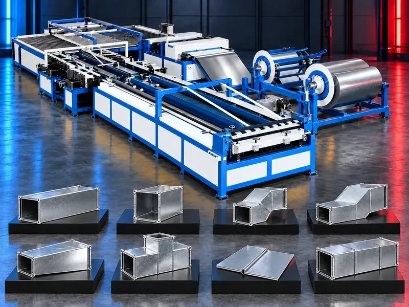
What the production line does
The line organizes several sheet metal preparation and forming stages into one controlled workflow for rectangular HVAC duct production. Available stations process coil material according to the approved job data and line configuration.
The production result depends on coil quality dimensional data tooling condition control settings material tracking and correct downstream assembly.
Production workflow
A typical verified workflow may start with coil loading and uncoiling followed by feeding leveling beading notching or punching shearing flange preparation locking and folding.
The exact sequence changes with the duct construction standard flange type section shape and options included in the supplied line.
Coil loading and uncoiling
Coil cradles support and feed selected sheet material into the line. Coil mass width inner diameter outer diameter and restraint method must match the approved loading equipment.
Safe coil handling requires a defined lifting route loading procedure guarding and controls that prevent uncontrolled rotation or sheet release.
Feeding leveling and positioning
The feeding system advances sheet metal to programmed positions while leveling helps control coil set before further processing. Servo driven or pneumatic handling may be included according to the verified design.
Confirm positioning method feed accuracy correction logic sheet support and response to slip deformation or interrupted cycles.
Beading and stiffening
Beading adds formed ribs that can improve panel stiffness and reduce vibration when specified by the duct design. Roller pattern depth spacing and orientation must suit the sheet thickness and finished duct dimensions.
Verify whether beading is standard optional or bypassable and confirm its effect on sealing folding and assembly.
Punching notching and shearing
Punching and notching prepare corner or connection details while shearing separates the programmed blank. Tool clearance blade condition and accurate positioning influence edge quality and dimensional consistency.
Confirm all required holes notches relief cuts corner patterns cut lengths and scrap handling against the approved duct drawing.
Locking and seam preparation
A fixed or integrated locking station may form longitudinal seam details without repeated movement of the blank between independent machines. The actual seam profile must match the assembly and leakage requirements.
Verify seam type usable thickness lubrication forming rolls adjustment and compatibility with the planned closing equipment.
Flange forming options
The line may route blanks through stations prepared for TDF flange angle steel flange or C shaped flange production when those modules are included. Each system uses different forming assembly sealing and reinforcement requirements.
Select the flange route from project specifications duct size pressure class connection method and approved installation practice.
Folding and U shaped sections
The folding station forms prepared blanks into the required U shaped or related duct section according to the verified cycle. Controlled stops and support help maintain dimensions and bend consistency.
Confirm the number of bends maximum fold length angle control minimum flange and how the folded section transfers to closing and assembly.
Control system and production memory
The control system may store dimensions job quantities and production records and coordinate the available stations. Clear recipes and controlled access reduce setup errors between orders.
Verify data fields order tracking memory capacity reports backup user permissions language support diagnostics and integration options before purchase.
Materials and duct construction
Provide the approved sheet grade coating thickness width surface condition and coil data. Galvanized sheet stainless steel or other materials require separate confirmation for tooling lubrication speed and corrosion control.
The line is not selected by material name alone because duct standard thickness flange system reinforcement and finished dimensions change the process requirement.
Productivity and material use
Useful output should be measured as accepted duct area or sections per shift under defined dimensions material thickness flange route staffing changeovers and downstream capacity.
Daily production cycle time and trim waste claims require a witnessed acceptance test using representative jobs and a documented measurement method.
Quality control
Acceptance should cover blank length width diagonals notch position flange geometry bead pattern fold dimensions seam fit edge condition surface damage and readiness for sealing and assembly.
Inspect the first piece after coil change tool adjustment recipe revision or maintenance and maintain traceable production records.
Safety and operator protection
The line contains rotating coils powered rolls punches shear blades folders transfer mechanisms and sharp sheet edges. Guards interlocks emergency stops safe control functions and controlled access should follow the approved risk assessment.
Safe procedures must cover coil loading setup trial cycles production unloading scrap removal jam recovery cleaning and maintenance.
Installation and factory layout
Site planning should confirm floor loading line length working clearances electrical supply compressed air hydraulic requirements lighting ventilation and access for service.
The layout should provide safe routes for coils blanks folded sections scrap tooling and finished ducts without crossing protected operating zones.
Training maintenance and lifecycle support
Training should cover job entry coil loading recipes station setup quality checks alarm recovery safe operation and daily care.
Preventive maintenance should address rolls bearings guides blades punches drives sensors cylinders lubrication electrical controls guards and safety devices. Prepare approved spare parts blades punches rolls and consumables.
How to select the correct line
Start with duct standards flange systems sheet materials thickness range coil data minimum and maximum duct sizes part mix shift target quality criteria and downstream assembly method.
Selection should then confirm the required stations automation level handling arrangement utilities factory layout staffing service scope and acceptance jobs.
Technical information requiring verification
Verify material types thickness range coil width coil weight coil diameters duct size range flange options forming stations feed accuracy cutting accuracy folding capacity speed output changeover waste utilities installed power air pressure hydraulic data dimensions floor load and total weight.
Confirm control hardware motion components electrical equipment coil cradles tray quantity conveyors locking stations flange modules folding station installation commissioning training warranty service scope spare parts and acceptance tests from approved documentation.
Publishing status
This page describes the production line category workflow and selection logic. Exact capacities output cycle time waste materials functions component sources standards and commercial commitments require an approved data sheet and technical review before publication.
Questions we are asked
What is a U shape automatic duct production line?
It is an integrated sheet metal forming line that prepares rectangular HVAC duct blanks or folded sections from approved coils through coordinated automated stations.
Which operations can be integrated?
The verified configuration may include uncoiling feeding leveling beading punching notching shearing locking flange forming and folding.
Which flange systems can the line support?
Possible routes may include TDF angle steel or C shaped flange preparation when the required modules tooling and control sequence are included and approved.
How is production capacity evaluated?
Capacity should be measured with representative duct sizes sheet thickness flange routes staffing changeovers and downstream assembly conditions during an agreed acceptance test.
How is material waste verified?
Waste should be measured for approved nesting logic trim allowances coil changes and representative orders rather than relying on a general supplier claim.
What information is needed for selection?
Provide duct standards flange systems sheet materials thickness range coil data duct dimensions product mix shift target quality requirements utilities and factory layout.
Tell us the part you need to make
An engineer reads every request. Usually the same working day.
Related
- Spiral Duct Forming Machine A forming machine for producing round spiral air ducts from compatible metal strip. Machine selection depends on duct diameter, material, strip thickness and width, seam type, cut length, and production target.
- Automatic Duct Production Line for Rectangular HVAC Ducts An automatic duct production line converts approved sheet metal coils into prepared rectangular HVAC duct blanks and folded sections through a coordinated linear workflow. Depending on the verified configuration it may integrate uncoiling leveling beading punching shearing transfer locking flange forming and folding
- Automatic Duct Blanking and Folding Production Line An automatic duct blanking and folding line converts approved sheet metal coils into prepared rectangular HVAC duct blanks and folded sections. The verified configuration may combine decoiling leveling beading corner notching shearing and hydraulic folding under CNC control.