

AUTOMATIC RECTANGULAR DUCT CORNER ASSEMBLY
Automatic Corner Code Assembly Machine for HVAC Ducts
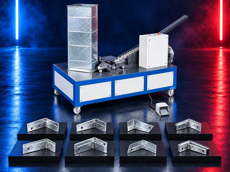
An automatic duct corner assembly machine positions and installs compatible corner pieces into the flange corners of rectangular HVAC duct sections. Correct selection depends on the corner drawing flange system duct dimensions material condition feeding method joining process and required production cycle
The machine receives a prepared rectangular duct section and a compatible corner piece then aligns and installs the corner through a controlled cycle. The exact insertion or fixing method must match the approved flange and corner design. Automatic handling can reduce repetitive manual corner installation and support more consistent positioning when duct preparation corner quality settings and feeding remain controlled. Claims for a six second cycle complete replacement of manual labor improved duct connection ease of operation or higher productivity require confirmation from the exact data sheet operating conditions representative trials and acceptance criteria.
What the machine does
The machine automates the positioning and installation of a prepared corner component at the corner of a rectangular duct flange. The completed corner supports later fastening sealing and duct connection operations.
The machine must be evaluated with the exact duct flange corner piece and installation requirement.
Corner piece compatibility
Provide the approved corner drawing with material thickness outside dimensions hole pattern bends radii and tolerances. Parts from different flange systems or dies may look similar but may not feed fit or lock correctly.
Verify corner orientation stacking condition burr limits coating condition and permitted variation from the approved corner production process.
Flange and duct compatibility
The duct flange must be formed square and remain within the dimensional tolerance required for corner insertion. Distorted open damaged or contaminated flange ends can cause poor location or incomplete installation.
Confirm compatible flange profiles duct width and height ranges flange thickness corner access and clearance around folds seams and reinforcement.
Automatic assembly cycle
A typical cycle includes duct positioning corner feeding orientation alignment insertion or fixing release and part removal. The actual sequence depends on the verified machine and tooling design.
Review each stage for controlled movement repeatable references fault detection and safe recovery before approving production.
Corner feeding and orientation
The feeding system must present one correct corner at the required orientation without double feeding jams or coating damage. Corner flatness burrs oil contamination and mixed sizes can affect reliable feeding.
Confirm feeder capacity refill method low level indication changeover cleaning and recovery from a misfeed.
Duct support and positioning
The duct section should be supported without sagging and placed against repeatable references. Large flexible or unbalanced sections may require adjustable tables stands or assisted handling.
Verify loading direction working height operator reach minimum and maximum duct sizes support spacing and discharge method.
Installation and fixing method
The corner may be inserted seated pressed or fixed according to the approved system. Applied force travel and tool geometry must install the part without deforming the flange damaging the coating or loosening the corner.
Confirm whether additional crimping fastening sealant or manual inspection is required after the automated cycle.
Quality control
Inspect corner seating orientation insertion depth flange squareness gaps deformation scratches coating damage retention and compatibility with later fastening and sealing.
Approve the first assembly after setup corner batch change flange change adjustment maintenance or stoppage and continue with a documented sampling plan.
Connection quality and leakage
Correct corner installation supports flange alignment but does not alone guarantee joint strength or leakage performance. Fasteners gaskets sealant duct squareness and field assembly also influence the final connection.
Define visual dimensional retention and leakage related acceptance criteria for the completed duct system.
Integration with corner production
A duct corner punching machine may produce the corner components before they are sorted inspected and supplied to the assembly machine. Compatibility between the approved die corner batch feeder and installation tooling must be controlled.
Trace corner type material batch and inspection status to prevent mixed or nonconforming parts from entering the feeder.
Integration in duct production
The assembly station normally follows sheet cutting beading notching flange forming folding lock forming seam closing and corner preparation. Fastening sealing gasket application and final inspection may follow corner installation.
Balance the station with upstream and downstream capacity and provide safe buffers without damaging unfinished ducts.
Productivity and labor
Accepted output depends on duct size handling corner refill cycle time fault recovery inspection changeover and surrounding process capacity. Labor needs depend on loading unloading replenishment quality checks and material movement.
Measure accepted assembled corners and completed ducts per shift during representative trials rather than relying on a single nominal cycle value.
Common process risks
Mixed corners poor flange forming bent parts burrs double feeding misorientation worn tooling incorrect settings or inadequate duct support can cause jams missing corners loose fit deformation or surface damage.
Stop the cycle and correct the corner flange feeder tooling or positioning condition when the assembly falls outside acceptance criteria.
Safety and operator protection
The machine may contain automatic feeders cylinders clamps moving tools pinch and crush points stored energy sharp sheet edges and sudden duct movement. Guards interlocks emergency stops controlled access and energy isolation must follow the approved risk assessment.
Procedures must cover loading replenishment setup trial cycles jam recovery manual removal cleaning tool work maintenance and safe release of stored energy.
Installation and site readiness
Confirm floor condition electrical and pneumatic services air quality working clearance duct support lighting noise control corner storage scrap control access and maintenance space.
The layout should separate incoming ducts corner containers accepted assemblies rejected parts and operator routes while protecting cables hoses and controls.
Training maintenance and lifecycle support
Training should cover corner and flange identification loading feeder refill setup references controls quality checks defect response safe recovery isolation cleaning and daily inspection.
Preventive maintenance should address feeders guides cylinders valves hoses sensors clamps tools stops guards controls lubrication fasteners and emergency devices. Prepare approved wear parts and critical spares.
How to select the correct machine
Start with corner drawings flange profiles duct size range materials production mix shift target utilities floor plan handling method and required changeover frequency.
Selection should confirm feeder compatibility installation method tooling force travel positioning support controls fault detection guarding maintenance service support and representative sample trials.
Technical information requiring verification
Verify compatible corner sizes and flange profiles duct dimensions corner material and thickness installation method force and travel feeder capacity cycle time output basis controls utilities air pressure and consumption electrical load accuracy noise dimensions and total weight.
Confirm supports guards standards corner tooling changeover data installation commissioning training warranty service scope spare parts and acceptance tests from approved documentation.
Publishing status
This page describes the machine category assembly process and selection logic. Exact cycle output compatibility capacities utilities controls standards and commercial commitments require an approved data sheet corner and flange drawings and technical review before publication.
Questions we are asked
What is a duct corner code assembly machine?
It is an automated station that positions and installs compatible corner components into the flange corners of rectangular HVAC duct sections.
Does it work with every corner and flange?
No. The corner drawing flange profile dimensions material and installation method must match the feeder tooling and machine settings.
Does it replace all manual work?
Automation can reduce repetitive installation but loading replenishment inspection handling setup and recovery tasks depend on the complete line configuration.
Does corner installation guarantee an airtight joint?
No. Joint performance also depends on flange quality duct squareness fasteners gaskets sealant and final assembly.
How is assembly quality checked?
Check corner orientation seating depth retention flange squareness deformation surface condition and fit with the specified fastening and sealing process.
What information is needed for selection?
Provide corner and flange drawings duct size range materials quantities utilities layout handling method quality criteria and representative samples.
Tell us the part you need to make
An engineer reads every request. Usually the same working day.
Related
- Spiral Duct Forming Machine A forming machine for producing round spiral air ducts from compatible metal strip. Machine selection depends on duct diameter, material, strip thickness and width, seam type, cut length, and production target.
- U Shape Automatic Duct Production Line A U shape automatic duct production line converts approved sheet metal coils into prepared duct sections through a coordinated sequence that may include uncoiling leveling beading punching shearing locking flange forming and folding. The correct configuration depends on duct type material thickness dimensions flange system output target and factory layout.
- Automatic Duct Production Line for Rectangular HVAC Ducts An automatic duct production line converts approved sheet metal coils into prepared rectangular HVAC duct blanks and folded sections through a coordinated linear workflow. Depending on the verified configuration it may integrate uncoiling leveling beading punching shearing transfer locking flange forming and folding