

Compact CNC Turning for Precision Components
Mini CNC Lathe Machine for Compact Precision Turning
A compact CNC lathe designed for controlled turning operations using a direct-drive spindle, brushless DC spindle motor, X/Z ball-screw feed system, manual 3-jaw chuck, configurable tool-post arrangement and manual tailstock.
The Mini CNC Lathe Machine is a compact CNC turning solution for workshops, training environments and production applications where a smaller machine footprint and controlled CNC operation are required. The supplied configuration uses a direct-drive spindle arrangement that eliminates the spindle-box gear transmission mechanism, simplifying the main drive structure. The spindle is driven by a brushless DC motor with stepless speed regulation. Forward and reverse spindle rotation are controlled through the electrical system, with the source information stating that both directions can operate at the same speed. For axis movement, the X and Z feed systems transmit motion through a two-step coupling arrangement using synchronous belts and pulleys connected to preloaded ball-screw nut pairs. This arrangement is intended to provide controlled, low-backlash feed transmission to the carriage and slide.
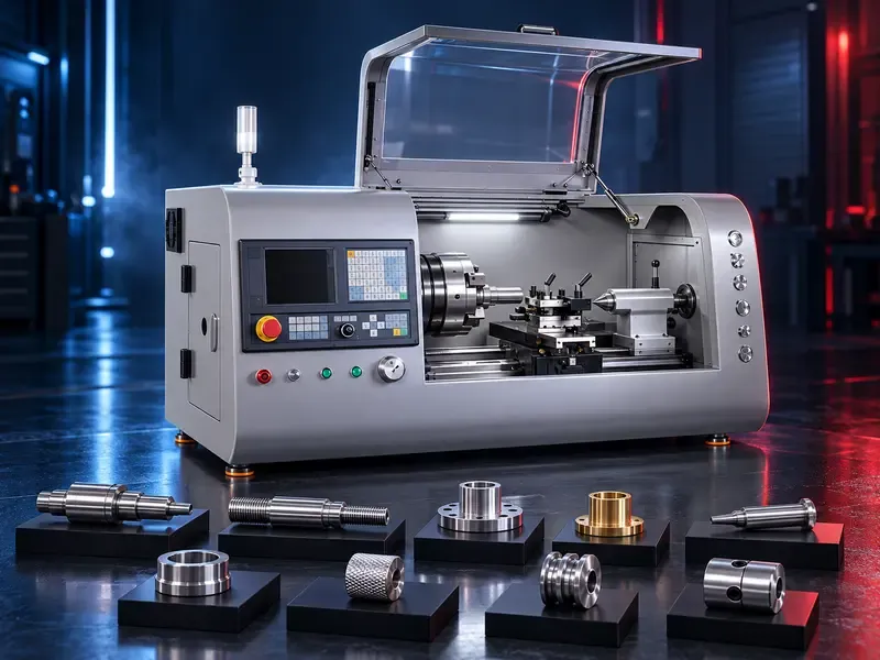
Machine Configuration & Main Systems
- Direct-drive spindle system with no spindle-box gear transmission mechanism.
- Brushless DC main spindle motor with stepless speed regulation.
- Electrical control of spindle forward and reverse rotation.
- Manual 3-jaw chuck for workpiece clamping.
- X-axis and Z-axis feed through synchronous-belt coupling and preloaded ball-screw nut pairs.
- Photoelectric spindle encoder driven through a synchronous belt and pulley arrangement.
- Tooling configuration can use two-row tool carriers and can also be equipped with a 4-station electric tool post.
- Manual tailstock with manual bed locking, handwheel sleeve movement and manual body positioning.
1. Main Drive System
The main motor directly drives the spindle. The spindle box does not use the conventional gear transmission mechanism described in the source, resulting in a simpler drive structure. The main drive uses a brushless DC motor and DC stepless speed regulation. Spindle forward and reverse rotation are controlled electrically.
2. Workpiece Clamping
The stated workpiece clamping configuration is a manual 3-jaw chuck. The operator manually clamps and releases the workpiece according to the machining setup.
3. X/Z Feed Drive System
X-axis and Z-axis feed motion is transferred through a two-step coupling arrangement. Synchronous belts and pulleys connect the drive to the ball-screw nut pair, which then transfers motion to the carriage or slide. The supplied information states that the ball-screw nut pair is preloaded to support high-precision, low-backlash transmission.
4. Photoelectric Encoder System
The spindle photoelectric encoder is driven by a synchronous belt. A pulley on the main spindle drives the corresponding pulley at the encoder assembly, allowing spindle rotational information to be transmitted to the CNC control system.
5. Tool Post Options
The machine can use two-row tool carriers and can be equipped with a 4-station electric tool post. For the electric tool-post configuration, indexing and locking are driven by the tool post built-in motor and controlled directly by the NC system.
6. Manual Tailstock
The tailstock is manually operated. It is manually locked on the bed using the stated eccentric locking principle. The handwheel moves the tailstock sleeve forward or backward, while releasing the locking mechanism allows the tailstock body to be repositioned along the bed. The sleeve must be locked before machining support is applied.
Typical Applications
- Small and medium-size turned components, subject to the selected machine capacity.
- Shaft-type and cylindrical component turning.
- Facing, external turning and internal turning when suitable tooling is installed.
- Training and CNC turning education environments.
- Prototype, maintenance and workshop turning tasks.
- Small-batch production where the selected machine travel, spindle and tooling capacity are suitable.
How to Select the Correct Mini CNC Lathe
- Maximum workpiece diameter and length required.
- Workpiece material and typical component geometry.
- Required spindle speed range and spindle motor rating.
- Chuck diameter and clamping method.
- X/Z axis travel and required machining envelope.
- Tool-post configuration: two-row carrier or 4-station electric tool post.
- Whether tailstock support is required for the intended parts.
- CNC control system and programming requirements.
- Required accuracy, repeatability and surface-finish targets.
- Electrical supply and workshop installation conditions.
Technical Data to Confirm Before Quotation
- Exact model: To be verified for the selected model.
- Swing over bed: To be verified for the selected model.
- Maximum turning diameter: To be verified for the selected model.
- Maximum workpiece length: To be verified for the selected model.
- Spindle bore: To be verified for the selected model.
- Spindle speed range: To be verified for the selected model.
- Spindle motor power: To be verified for the selected model.
- Chuck size: To be verified for the selected model.
- X-axis travel: To be verified for the selected model.
- Z-axis travel: To be verified for the selected model.
- Rapid traverse/feed rates: To be verified for the selected model.
- Ball-screw specification: To be verified for the selected model.
- Tool-post type and number of stations: To be verified for the selected model.
- Tailstock taper and sleeve travel: To be verified for the selected model.
- CNC controller: To be verified for the selected model.
- Positioning accuracy and repeatability: To be verified for the selected model.
- Machine dimensions and net weight: To be verified for the selected model.
- Electrical supply and total installed power: To be verified for the selected model.
Information Required for a Quotation
- Workpiece drawing or clear part photo
- Material
- Maximum diameter and length
- Required machining operations
- Expected batch quantity / production volume
- Required tolerance and surface finish
- Preferred chuck and tool-post configuration
- Whether a tailstock is required
- Electrical supply
- Any preferred CNC control system
Questions we are asked
What is a Mini CNC Lathe Machine?
It is a compact CNC turning machine intended for controlled machining of rotational components within the capacity of the selected model.
How is the spindle driven?
The supplied configuration uses a direct-drive spindle arrangement powered by a brushless DC motor with stepless speed regulation.
Does the machine use a manual or power chuck?
The supplied configuration specifies a manual 3-jaw chuck.
How are the X and Z axes driven?
The X and Z feed systems use synchronous-belt coupling connected to preloaded ball-screw nut pairs.
What tool-post options are available?
The supplied information states that the machine can use two-row tool carriers and can be equipped with a 4-station electric tool post.
Does the machine have a tailstock?
Yes. The supplied configuration describes a manually positioned and manually operated tailstock.
Can exact capacities be published for every Mini CNC Lathe?
No. Turning diameter, length, spindle speed, motor power, travels and other numerical specifications must be confirmed from the datasheet of the exact selected model.
Tell us the part you need to make
An engineer reads every request. Usually the same working day.
Related
- VICTOR Slant-Bed CNC Lathes Slant-bed CNC turning machines from VICTOR Taichung for machining shafts, bushings, flanges, threaded parts, and other rotational components. The appropriate model is selected according to the workpiece, operations, accuracy, and production requirements.
- CNC Vertical Machining Center (VMC) Vertical CNC machining solutions for milling, drilling, tapping and producing engineered metal components.
- CNC Wire EDM Machines Precision machining solutions for producing complex profiles in electrically conductive materials using a CNC-controlled wire electrode.