

CNC Routing & Milling for Aluminum Fabrication
Aluminum CNC Router for Non-Ferrous Machining
CNC routing and milling solution for aluminum sheets, plates, composite panels and suitable profiles — configured around workpiece size, alloy, thickness, tolerance, surface finish, production volume and automation requirements.
SAKKARY MACHINERY provides Aluminum CNC Router solutions for non-ferrous fabrication applications requiring controlled cutting, profiling, pocketing, drilling, engraving and milling of suitable aluminum workpieces. Machine selection should begin with the actual workpiece: aluminum grade and hardness, thickness range, maximum sheet or profile dimensions, smallest internal features, required tolerances and surface-finish target. The production requirement then determines the working area, Z-axis clearance, spindle characteristics, drive system, workholding method and automation options. Configurations can include vacuum or T-slot workholding, pneumatic clamping, automatic tool changing, tool-length sensing and rotary-axis options where suitable. Final spindle power, speed, feed rate, travel, accuracy, table size and other technical specifications must be confirmed from the exact machine configuration before publication or quotation.
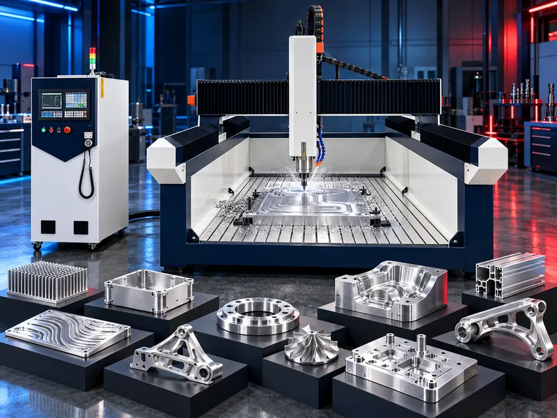
What it is for
- Aluminum sheet and plate routing, profiling and contour cutting
- Pocketing, slotting, drilling and engraving
- Aluminum Composite Panel (ACP) processing where compatible with the selected tooling and process
- Fabrication of suitable aluminum profiles and non-ferrous components
- Nested part production on sheet material with suitable workholding
- Multi-tool machining when configured with an Automatic Tool Changer (ATC)
- Multi-sided or cylindrical work using an optional rotary fourth-axis configuration where applicable
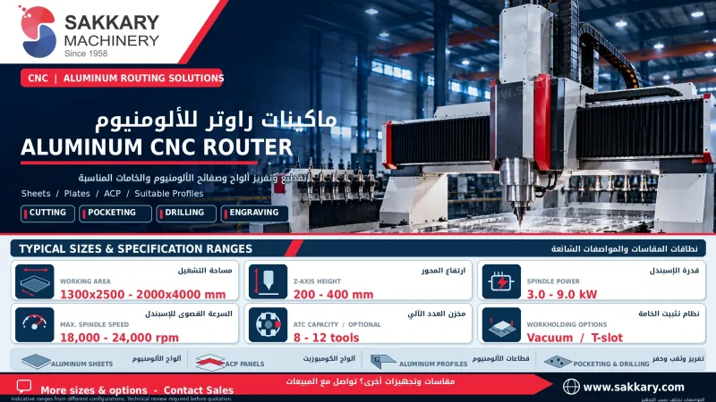
Selection Guide & Configurator Matrix
- Step 1: Define Workpiece Parameters & Material Grades Specify the alloy grade and hardness, material thickness range, maximum stock dimensions and the smallest internal feature radii or hole diameters. These inputs influence machine rigidity, working area, Z-axis clearance, tooling and spindle requirements.
- Step 2: Establish Quality, Tolerance & Surface Finish Targets Define the required dimensional tolerance, repeatability and surface finish. These requirements help determine the appropriate motion system, drive configuration, structural rigidity, tooling and lubrication or cooling approach.
- Step 3: Evaluate Throughput Dynamics & Capacity Cycles State the intended daily runtime, target cycle time and expected production volume. These values are required to size the machine for the intended duty pattern and to evaluate automation and material-handling needs.
- Step Optimize Fixturing, Workholding & Workflow Processing Select workholding according to the part: multi-zone vacuum tables can support suitable sheet nesting, while T-slot or pneumatic clamping can be considered for thicker plates, profiles and components. Positioning pins or alignment systems may be added where required.
- Step 5: Select Performance Automation & Production Upgrades
Depending on the job, options can include an Automatic Tool Changer, rotary fourth axis, automatic tool-length sensor, positioning systems and other production upgrades. Exact availability depends on the selected machine configuration.
Information required to configure the machine
- Aluminum alloy or material type
- Minimum and maximum thickness
- Maximum sheet, plate or profile dimensions
- Part drawing / CAD file where available
- Smallest hole, slot or internal radius
- Required operations: cutting, profiling, pocketing, drilling, engraving or milling
- Required tolerance and surface finish
- Daily runtime and expected production volume
- Preferred workholding method
- Need for ATC, rotary axis, tool sensor or automated positioning
How to choose the right Aluminum CNC Router
- Prioritize the machine configuration that can meet the actual tolerance and repeatability required by the part.
- Evaluate spindle, tooling, feed strategy and tool paths around aluminum machining rather than selecting by working area alone.
- Consider surface-finish requirements together with machine rigidity, workholding, tooling and lubrication or cooling strategy.
- Compare the complete production setup — machine, tooling, workholding, automation and operating requirements — rather than initial machine price alone.
- Choose a configuration that can adapt to the expected product mix and future production requirements without adding unnecessary options.
Questions we are asked
What is an Aluminum CNC Router?
An Aluminum CNC Router is a CNC machining system configured for routing, cutting, drilling, engraving, pocketing and milling suitable aluminum and other compatible non-ferrous workpieces. The exact capability depends on the machine structure, spindle, tooling, workholding and control configuration.
What information is needed before selecting the machine?
Provide the aluminum grade, thickness range, maximum workpiece size, part drawing, required operations, tolerance, surface finish and expected production volume. These inputs are more useful than selecting a machine from table size alone.
Can it machine 6061-T6 or 5052 aluminum?
These are common aluminum grades considered in CNC machining, but suitability and cutting parameters must be confirmed for the exact machine, spindle, tooling, workholding and part requirements.
Can the router process Aluminum Composite Panels?
It can be configured for compatible aluminum composite panel applications when the tooling, cutting method, workholding and extraction requirements are suitable for the material.
Should I choose a vacuum table or T-slot clamping?
Vacuum workholding can be useful for suitable sheet and nesting applications. T-slot or pneumatic clamping may be more appropriate for thicker plates, profiles or parts requiring stronger mechanical restraint. The part geometry and cutting forces determine the correct method.
When is an Automatic Tool Changer useful?
An ATC is useful when one component requires several tools or operations, such as drilling, pocketing and profiling, because it can reduce manual tool-change intervention. The number and type of tools should be defined from the actual process.
Can a rotary fourth axis be added?
A rotary-axis configuration can be considered for compatible cylindrical or multi-sided work. Availability, workpiece diameter, length and machining method must be confirmed for the selected machine.
What accuracy can the machine achieve?
Accuracy is configuration-specific. Values such as ±0.05 mm should only be published when verified for the exact machine under defined operating and test conditions.
What technical data should be confirmed before ordering?
Confirm working area, Z travel and clearance, spindle power and speed, feed and rapid speeds, drive system, accuracy and repeatability, table and clamping system, controller, ATC capacity if fitted, electrical requirements, lubrication or cooling arrangement, dimensions and weight.
Tell us the part you need to make
An engineer reads every request. Usually the same working day.
Related
- VICTOR Slant-Bed CNC Lathes Slant-bed CNC turning machines from VICTOR Taichung for machining shafts, bushings, flanges, threaded parts, and other rotational components. The appropriate model is selected according to the workpiece, operations, accuracy, and production requirements.
- CNC Vertical Machining Center (VMC) Vertical CNC machining solutions for milling, drilling, tapping and producing engineered metal components.
- CNC Wire EDM Machines Precision machining solutions for producing complex profiles in electrically conductive materials using a CNC-controlled wire electrode.