

5 AXIS CNC MACHINING CENTERS
5 Axis Gantry Machining Centers
A 5 axis gantry machining center combines a large bridge structure with coordinated linear and rotary axes for supported machining of dies, molds, tooling, structural components, and complex surfaces. The correct configuration depends on the part size, material, geometry, tolerances, finish, table load, spindle, head kinematics, automation, and required output.
A 5 axis gantry machining center positions the cutting tool through three linear axes and two rotary axes so it can approach complex features from controlled orientations. The gantry layout can provide a large working envelope while keeping the workpiece on a table or foundation mounted fixture. The supplied description refers to box in box construction, linear motors, cooled ball screws, a direct drive head, thermal compensation, high rapid movement, full enclosure, and advanced coolant and chip systems. These are configuration claims that must be confirmed from approved technical documents for the selected machine before publication or selection.
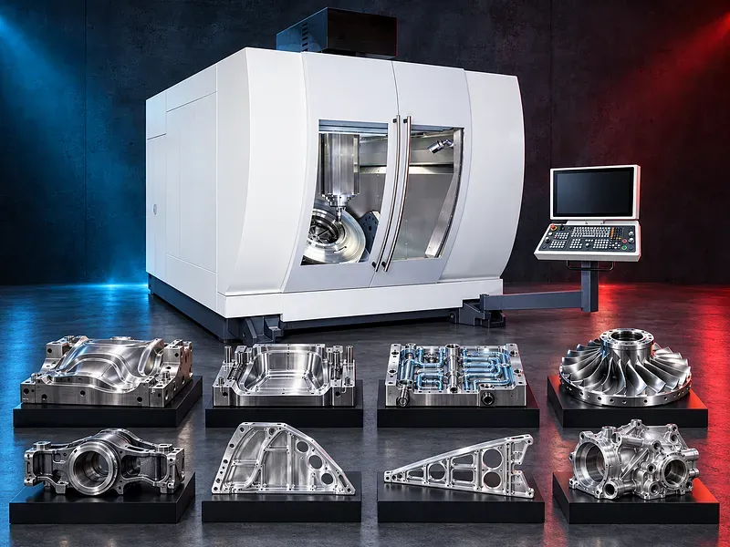
5 axis gantry machining concept
The machine coordinates linear and rotary axes to control tool position and orientation relative to the workpiece. This can support simultaneous contouring or indexed multi side machining according to the verified CNC, head, kinematics, software, and program.
Five axis capability does not by itself guarantee accuracy or collision free machining. Machine geometry, rotary center calibration, tool data, postprocessor quality, setup, thermal condition, and verification all affect the result.
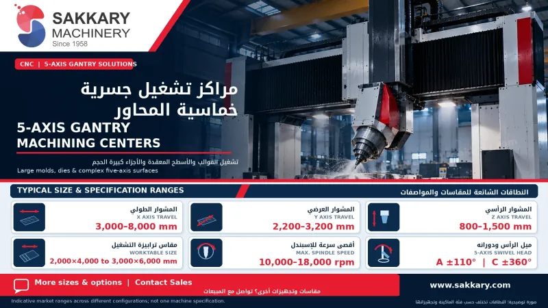
Gantry and bridge structure
A gantry structure places the crossrail or bridge over the work area and supports the moving head or ram. Designs may use fixed or moving bridges, fixed or moving tables, raised columns, symmetrical structures, or other arrangements.
Box in box symmetry, cast structures, welded structures, guideway arrangement, span, crossrail support, and center of gravity should be evaluated from verified engineering data rather than marketing descriptions alone.
Five axis head and rotary kinematics
Potential head configurations include fork heads, universal heads, orthogonal heads, direct drive rotary heads, geared heads, or exchangeable heads. Rotary axes may be located in the head, table, or a combined arrangement.
Head range, torque, speed, clamping, encoder feedback, pivot length, cable routing, cooling, collision envelope, tool center point control, and calibration method require exact technical confirmation.
Linear axis drives and vertical support
Linear axes may use ball screws, rack systems, linear motors, hydrostatic systems, or other verified drive arrangements. The vertical axis may use counterbalance, dual drives, brake systems, or another support method.
The supplied description mentions linear motors, dual cooled ball screws, and closed loop counterbalance. Their availability, axis assignment, cooling circuit, force, accuracy, service requirements, and safety functions need approved documentation.
Large dies molds and tooling
Potential work includes stamping dies, forming tools, injection mold components, compression molds, die casting molds, fixture structures, and other large tooling that needs deep cavities, freeform surfaces, holes, pockets, and controlled datum relationships.
Application suitability depends on part size and weight, material, hardness, stock condition, feature access, tool length, spindle performance, workholding, finishing requirement, and inspection plan.
Aerospace energy and structural components
Potential applications may include supported aerospace frames, ribs, bulkhead type structures, housings, energy components, turbine related parts, transportation components, and heavy industrial structures when the machine and process meet the drawing.
Thin walls, large aluminum parts, hard alloys, castings, welded structures, and heavy components create different requirements for support, vibration control, chip evacuation, heat management, probing, toolpaths, and inspection.
Materials and cutting strategy
Potential materials may include suitable aluminum alloys, steels, tool steels, cast irons, nonferrous alloys, and other machinable materials after reviewing grade, hardness, heat treatment, stock condition, residual stress, chip behavior, and surface requirements.
Roughing, semi finishing, finishing, rest machining, five axis contouring, drilling, and supported milling cycles should be planned around the material, tool, spindle, head orientation, rigidity, accessibility, and thermal behavior.
Spindle and cutting head selection
Spindle selection should consider material, tool diameter, cutting speed, torque at working speed, power, taper, holder retention, duty cycle, bearings, cooling, runout, tool length, and expected cutting load.
A direct drive head or high speed spindle may support some finishing work, while heavier roughing may require a different torque and rigidity balance. The verified torque and power curves should guide selection.
Tooling and tool management
Potential tooling includes face mills, end mills, ball nose tools, barrel tools, drills, reamers, boring tools, chamfer tools, holders, extensions, shrink systems, hydraulic holders, and probes compatible with the spindle and process.
Tool length, diameter, projection, balance, runout, holder condition, tool change limits, adjacent pocket restrictions, measurement, wear compensation, breakage detection, and replacement strategy should be controlled.
Workholding table and part access
The fixture should locate the component from defined datums and resist cutting forces, torque, vibration, lifting, and axis acceleration without unacceptable distortion. Clamps must preserve tool access, head rotation, chip flow, probing, and inspection.
Table dimensions, allowable load, load distribution, fixture height, part swing, bridge clearance, tool reach, head envelope, loading path, and collision zones must be checked using the actual part and fixture.
CAM postprocessor and simulation
Complex five axis machining normally requires verified CAM toolpaths and a postprocessor matched to the actual CNC, kinematic chain, axis limits, rotary direction, pivot data, and machine options.
Machine simulation, collision checking, tool and holder models, fixture models, safe approach moves, singularity review, axis rewind strategy, dry run, and controlled first part approval are essential process controls.
Probing calibration and compensation
Work probes, tool setters, spindle probes, calibration spheres, lasers, or other measurement systems may support work offset setting, part alignment, tool measurement, rotary center calibration, and in process checks when provided.
Probe accuracy, cycles, calibration interval, reference artifacts, thermal state, software options, compensation logic, and traceability must be verified for the required result.
Thermal management and process stability
Thermal management may include spindle cooling, screw or motor cooling, coolant temperature control, scale feedback, structural symmetry, warm up cycles, environmental control, and software compensation.
Thermal compensation does not guarantee accuracy under every condition. Machine load, ambient temperature, duty cycle, coolant condition, axis movement, setup, material stress, and inspection timing remain important.
Coolant chip evacuation and enclosure
Large cavities and long cycles can generate significant chips and heat. Coolant delivery, through tool supply, flushing, mist control, filtration, chip conveyors, bed wash, cleaning access, and planned chip removal should match the material and process.
A full enclosure may improve containment, but its exact coverage, access doors, windows, roof, interlocks, extraction integration, and ability to contain chips, coolant, or tool breakage require verification.
Accuracy surface finish and inspection
Acceptance may cover dimensions, position, profile, surface contour, flatness, perpendicularity, hole spacing, bore condition, surface finish, blend marks, tool marks, and relationships between features on several orientations.
Results can be affected by machine geometry, rotary calibration, axis feedback, head stiffness, tool deflection, spindle condition, fixture stiffness, material stress, thermal growth, toolpath, cutting data, and measurement uncertainty.
Productivity and cycle time
Five axis access may reduce manual reclamping, separate fixtures, and intermediate handling when the part and process benefit from machining several orientations in one controlled setup.
Claims for rapid movement, cycle time reduction, scrap reduction, tool life, repeatability, or cost per part require validation using the actual program, material, tools, setup, inspection, and approved acceptance criteria.
How to choose the correct machine
Provide three dimensional models and drawings, material and heat treatment, raw stock dimensions, finished part size and weight, feature access, tolerances, finish, quantities, batch sizes, fixture concept, current process, and target output.
Selection should review axis travels, bridge span, vertical clearance, table dimensions and load, head kinematics, rotary ranges, spindle torque and power, rapid and feed rates, tool capacity, probing, thermal systems, chip control, enclosure, accuracy tests, CAM, utilities, foundation, and future parts.
Technical information to verify
Approved technical documents must confirm the machine structure, axis configuration, controlled axes, travels, clearances, table dimensions and load, bridge span, head type, rotary ranges, axis drives, rapid rates, feed rates, acceleration, spindle taper, speed, torque, power, and tool capacity.
They must also confirm positioning accuracy, repeatability, volumetric or rotary performance, test standard and conditions, thermal systems, scales, compensation, CNC functions, tool changer, probes, coolant, chip conveyors, enclosure, electrical supply, air, dimensions, weight, foundation, software, included equipment, and options.
Safety and operating risks
The risk assessment should cover large moving axes, rotating tools, head rotation, tool change, crushing and collision zones, tool breakage, hot chips, coolant, heavy fixtures, suspended loads, access at height, hydraulic or pneumatic pressure, electrical hazards, stored energy, and maintenance isolation.
Required controls may include verified guarding and interlocks, emergency stops, safe access platforms, lifting plans, secure workholding, collision prevention procedures, safe chip removal, suitable personal protection, training, and documented lockout procedures.
Installation maintenance and lifecycle support
Site planning should cover foundation engineering, floor and soil conditions, anchoring, leveling, electrical supply, grounding, compressed air, coolant, chip handling, extraction, ventilation, cranes, loading routes, access platforms, temperature control, network needs, and maintenance clearance.
Preventive maintenance should follow approved documents for guideways, screws or linear drives, scales, spindle, head rotary axes, lubrication, cooling circuits, counterbalance, hydraulics, coolant, conveyors, tool changer, probes, enclosure, electrical cabinets, backups, alignment, and calibration.
Limitations and alternative processes
A five axis gantry center requires substantial investment in foundation, tooling, CAM, postprocessing, verification, lifting, inspection, training, and maintenance. It may not be the most efficient choice for small simple parts or work that needs only three axis machining.
Depending on the component, alternatives may include a three axis gantry mill, bridge machining center, floor type boring mill, horizontal machining center, vertical machining center, five axis table machine, mill turn center, or dedicated production system.
Technical review and next step
Send part models and drawings, material and heat treatment data, raw and finished dimensions, weight, tolerances, surface requirements, annual and batch quantities, current process, target output, site utilities, floor plan, crane data, and handling method for technical review.
The technical review will identify the suitable working envelope, structure, head kinematics, spindle, tooling, fixture, CAM and postprocessor needs, probing, thermal controls, chip system, inspection plan, installation needs, and any sample machining requirement.
Questions we are asked
What is a 5 axis gantry machining center?
It is a gantry style CNC machining center that coordinates three linear axes and two rotary axes to control tool position and orientation around supported large or complex parts.
What parts can it machine?
Potential work includes large dies molds tooling aerospace structures energy components and heavy structural parts when the working envelope head spindle setup and accuracy meet the drawings.
Does every machine use linear motors and a direct drive head?
No. Axis drives head construction spindle and thermal systems vary by configuration and require approved technical verification.
Can five axis machining reduce setups?
Potentially yes when several supported orientations can be machined in one controlled fixture. Actual savings depend on the part toolpaths tooling probing inspection and process plan.
What software is required?
Complex work normally needs suitable CAM a verified machine postprocessor machine simulation collision checking and controlled program prove out.
What information is required for selection?
Provide three dimensional models drawings material raw and finished size part weight tolerances surfaces quantities current process target output utilities floor plan crane data and handling method.
Tell us the part you need to make
An engineer reads every request. Usually the same working day.
Related
- VICTOR Slant-Bed CNC Lathes Slant-bed CNC turning machines from VICTOR Taichung for machining shafts, bushings, flanges, threaded parts, and other rotational components. The appropriate model is selected according to the workpiece, operations, accuracy, and production requirements.
- CNC Vertical Machining Center (VMC) Vertical CNC machining solutions for milling, drilling, tapping and producing engineered metal components.
- CNC Wire EDM Machines Precision machining solutions for producing complex profiles in electrically conductive materials using a CNC-controlled wire electrode.