

CNC-Controlled Hydraulic Corner Joining for Aluminium Profiles
CNC Aluminium Profile Corner Crimping Machine
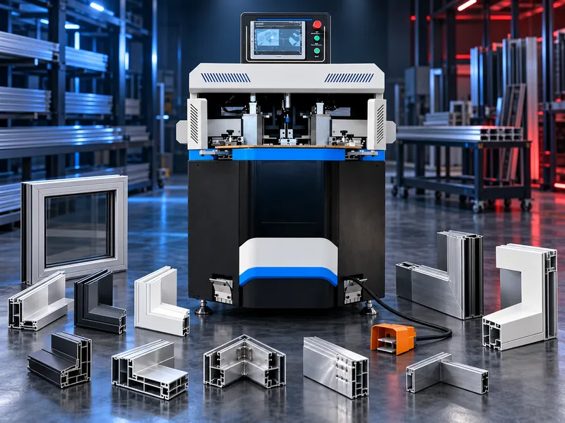
A CNC-controlled hydraulic corner crimping machine for assembling aluminium profile frames used in doors, windows, architectural systems and suitable industrial profile applications. The machine combines programmable knife positioning, synchronized crimping action and adjustable tooling to support repeatable 90-degree corner joining.
The CNC aluminium profile corner crimping machine is designed for joining prepared aluminium profiles at frame corners. A compatible corner cleat or connector is inserted into the profile cavities, the two prepared profiles are aligned to form the required corner, and crimping knives mechanically deform the profile walls into the connector to lock the joint. The current SAKKARY MACHINERY product information specifies CNC positioning with a touch-screen interface, hydraulic crimping force, synchronized dual-knife movement, adjustable tooling and foot-pedal operation. The supplied product information also states positioning accuracy of ±0.1 mm for the crimping knives. The quality of the finished corner does not depend on the machine alone. Profile cutting accuracy, end preparation, corner-cleat compatibility, knife position, tooling setup, clamping, profile wall thickness and operator alignment all influence the final frame geometry and joint quality. Machine selection should therefore be based on the actual aluminium profile section and corner-joint design. The profile drawing or physical sample, section dimensions, wall thickness, cleat geometry, required crimping points and expected production volume should be reviewed before quotation
- 90-degree corner joining of compatible aluminium profiles
- Mechanical crimping of profile walls into a compatible corner cleat/connector
- Assembly of aluminium door and window frames
- Assembly of suitable architectural aluminium frames
- Repeatable positioning of crimping knives using CNC control
- Hydraulic application of crimping force
Typical Applications
- Aluminium window frames
- Aluminium door frames
- Architectural aluminium systems
- Suitable curtain-wall profile assemblies
- Aluminium frame fabrication
- Industrial aluminium profile frames with compatible corner-joint designs
How the Corner Crimping Process Works
- Profiles are cut and prepared to the required corner geometry.
- A compatible corner cleat/connector is inserted into the profile cavities.
- The profiles are brought together and aligned at the corner.
- The profile and joint are positioned against the machine locating system.
- Crimping-knife positions are set for the profile and cleat geometry.
- The hydraulic crimping cycle drives the knives into the profile walls at the specified positions.
- The joint is released and checked for alignment, dimensions and connection quality.
CNC Positioning & Control
- Touch-screen CNC interface according to the current product information
- Programmable positioning of the crimping operation
- Specified knife-positioning accuracy of ±0.1 mm according to supplied product information
- Repeatable setup for recurring profile families where supported by the controller
- Reduced manual adjustment compared with fully manual positioning methods
Hydraulic Crimping System
- Hydraulic station provides the force for corner crimping
- Controlled crimping action for profile-to-cleat mechanical locking
- Suitable for production environments requiring consistent joining force
- Final hydraulic pressure, motor power and force must be confirmed from the selected model specification
Synchronized Dual Crimping Knives
The current product description specifies synchronized dual-knife movement. Coordinated knife action helps apply crimping on both sides of the corner joint in an aligned manner and can reduce uneven loading or asymmetric deformation when the machine is correctly set up.Adjustable Tooling
- Knife position adjustment for different profile/joint geometries within the verified working range
- Adjustment for different profile heights and widths subject to machine capacity
- Tooling setup based on cleat position and profile wall geometry
- Profile-specific tooling may be required for unusual or special sections
Foot-Pedal Operation
Foot-pedal actuation allows the operator to keep both hands available for profile positioning and alignment during the joining cycle. The exact sequence of clamping and crimping must follow the selected machine operating instructions and safety system.Profile & Corner Cleat Requirements
- Aluminium profile cross-section drawing or sample
- Profile width and height
- Wall thickness at the crimping area
- Corner-cleat dimensions and material
- Cleat position inside the profile cavity
- Required crimping-point locations
- Required corner angle and finished frame geometry
- Visible/cosmetic surfaces that must be protected
Factors That Affect Corner Quality
- Accuracy of the 45-degree or required profile cuts
- Profile end preparation and cleanliness
- Correct corner-cleat size and fit
- Correct knife height, depth and lateral position
- Consistent profile locating and clamping
- Profile alloy, temper and wall thickness
- Crimping force and tooling condition
- Frame support during assembly
- Inspection of diagonal dimensions and corner alignment
Quality Checks After Crimping
- Corner angle and visual alignment
- Frame diagonal dimensions where applicable
- Joint closure and visible gaps
- Profile surface condition
- Crimp indentation position and consistency
- Mechanical security of the corner joint according to the approved assembly method
- Repeatability across production batches
How to Select the Correct Machine
- Send the aluminium profile cross-section drawing or a physical sample.
- Provide profile width, height and wall thickness.
- Provide the corner-cleat drawing or sample.
- Identify the required crimping points and their positions.
- Confirm the frame application: window, door, facade or industrial frame.
- State the profile alloy/temper if known.
- Define expected production volume or frames per shift.
- Confirm whether recurring profile recipes/programs are required.
- Identify cosmetic surfaces and acceptable marking.
- Confirm electrical, pneumatic and workshop requirements for the selected model.
Information Required for Quotation
- Profile cross-section drawing (PDF/DXF/DWG if available)
- Profile sample if available
- Profile width and height
- Wall thickness
- Aluminium alloy/temper if known
- Corner-cleat drawing, dimensions or sample
- Required crimping positions
- Frame/product drawing
- Production quantity or target output
- Required CNC functions or recipe storage
- Utilities and installation location
Questions we are asked
What is a CNC aluminium profile corner crimping machine?
It is a hydraulic profile-joining machine used to assemble compatible aluminium profile corners by mechanically crimping the profile walls into a corner cleat or connector.
What is a corner cleat?
A corner cleat is a connector fitted inside compatible aluminium profile cavities to join two profile sections at a corner. The crimping knives deform the profile into the cleat to mechanically lock the joint.
What is the machine mainly used for?
Typical applications include aluminium door and window frames, architectural aluminium systems and suitable industrial aluminium profile frames.
What accuracy is specified on the current product page?
The supplied product information states ±0.1 mm positioning accuracy for the crimping knives. Finished-frame accuracy also depends on cutting, preparation, tooling, cleat fit, setup and alignment.
Why are synchronized dual knives used?
Synchronized movement helps apply the crimping action in a coordinated way on both sides of the joint, supporting balanced joining when the machine is correctly set.
Can the machine work with different profile sizes?
The current product information describes adjustable tooling for different profile heights and widths. Exact minimum and maximum dimensions must be confirmed for the selected model.
Does every aluminium profile use the same corner cleat and knife setting?
No. Profile cavities, wall thicknesses and joint designs differ, so cleat geometry and crimping positions must match the actual profile system.
Does the machine automatically guarantee a square frame?
No. Correct cutting, profile preparation, cleat fit, locating, support and inspection are also required to achieve the intended frame geometry.
Why is the profile drawing important before quotation?
The drawing shows the profile cavities, wall thickness and crimping area, which are necessary for checking tooling, knife positions and machine working range.
What should I send SAKKARY MACHINERY for machine selection?
Send the profile drawing or sample, dimensions, wall thickness, cleat details, crimping positions, finished frame/application and expected production volume.
Tell us the part you need to make
An engineer reads every request. Usually the same working day.
Related
- Aluminum Profile End Milling Machine End milling solutions for preparing aluminum profile ends for accurate fitting and assembly in suitable window, door and facade systems.
- Automatic Up Cut Mitre Saw for Aluminium and PVC An automatic up cut mitre saw uses a guarded blade that rises through the work area to cut approved aluminium and PVC profiles at straight or angled settings supported by the machine. Correct selection depends on profile material cross section length cut angles finished quality blade clamping feeding cooling extraction output target utilities and safety requirements.
- Double Head Mitre Saw for Aluminium and PVC A double head mitre saw cuts both ends of an approved aluminium or PVC profile to the required length and supported angles within one coordinated cycle. Correct selection depends on profile material cross section finished length angle combination cut quality blade configuration head positioning clamping support output utilities and safety requirements.