

TWO END PROFILE CUTTING IN ONE CYCLE
Double Head Mitre Saw for Aluminium and PVC
A double head mitre saw cuts both ends of an approved aluminium or PVC profile to the required length and supported angles within one coordinated cycle. Correct selection depends on profile material cross section finished length angle combination cut quality blade configuration head positioning clamping support output utilities and safety requirements.
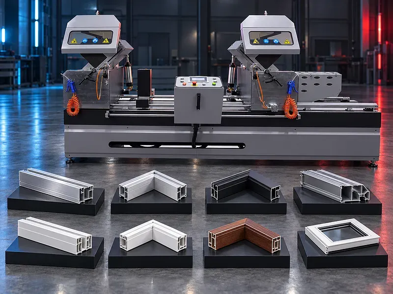
One saw head normally remains at a reference position while the other moves to establish the programmed or measured cutting length. The profile is supported and clamped before the two heads complete the approved end cuts. The machine is commonly considered for window door facade partition and furniture profile fabrication. Exact length range angle positions simultaneous cutting functions software accessories and material compatibility must be confirmed from approved technical documentation.
What the machine does
The machine establishes the distance between two cutting heads according to the required finished length. After the profile is referenced and clamped each head performs its selected straight or mitre cut according to the approved cycle.
Processing both ends without moving the part to another saw can reduce repeated measurement and help preserve the relationship between length and end angles.
Two head working principle
The fixed and movable heads create two controlled cutting references. Head position angle setting clamps blades and profile supports must remain coordinated throughout the cycle.
Confirm whether the heads cut simultaneously or sequentially and how the control prevents collision or an unsafe cycle at short lengths.
Length positioning
The movable head may be positioned manually or through a controlled axis depending on configuration. A verified reference system measures the distance between the cutting planes.
Confirm usable minimum and maximum lengths positioning method calibration compensation and measurement of finished parts.
Straight and mitre angles
Each head may support square cuts and approved mitre positions. Available inward and outward angle combinations indexing and automatic positioning depend on the supplied design.
Review actual frame joint drawings because the two end angles and profile orientation determine whether the part can be processed in one loading.
Aluminium profile applications
Approved aluminium extrusions for windows doors facades partitions furniture and industrial frames may be cut when their alloy temper wall thickness and cross section suit the cutting envelope and blade.
Thermal breaks chambers thin walls coatings and protective films require suitable blade geometry support clamping and lubrication.
PVC profile applications
Approved rigid PVC profiles may be cut when blade geometry speed feed support and clamping prevent melting cracking chipping or deformation.
Profiles containing reinforcement seals films or inserted parts require a process review and may need a different blade or operating setup.
Profile support and loading
The profile should be supported along its length so it remains stable and aligned with both cutting heads. Long flexible or finished sections may require intermediate supports and protective contact surfaces.
Define loading direction reference side stock length maximum weight and safe handling of completed parts and offcuts.
Automatic clamping
Horizontal or vertical clamps secure the profile before blade movement and release it only after both heads reach their safe states. Pressure and clamp location should prevent movement without crushing the section.
Verify contact pads pressure adjustment sensors and compatibility with narrow hollow asymmetrical and surface finished profiles.
Blade selection and cutting process
Blade diameter bore tooth geometry kerf material and approved speed must match each saw head and the material. Aluminium and PVC may require separate blade specifications and cutting parameters.
Use approved sharp balanced blades and control blade installation rotation condition sharpening and replacement.
Lubrication and chip control
Aluminium may require an approved lubricant application to limit heat chip adhesion and surface damage. PVC requires controlled cutting conditions that avoid excessive heat and smearing.
Provide chip collection or extraction suitable for both heads and define cleaning of guards fences clamps and sensors.
Cut quality and inspection
Acceptance should define finished length both end angles squareness burr level edge finish deformation and joint fit from approved drawings. Inspect the first component after setup blade change or program revision.
Use calibrated length and angle measurement methods that match the specified tolerance and product assembly requirement.
Production control
Controlled head positioning and stored cut data may support repeat and mixed length production when included. Practical output also includes loading angle changes clamping cutting unloading inspection and offcut handling.
Evaluate representative cut lists batch sizes profile changes angle combinations and operator tasks before approving productivity.
Safety and operator protection
The machine includes two high speed blades automatic clamps a moving head sharp profiles and ejected chips. Guards interlocks emergency stops safe head movement and protective equipment should follow the approved risk assessment.
Safe procedures must cover loading head positioning angle setup blade changes trial cuts offcut removal cleaning jam recovery and maintenance.
Installation and site readiness
Site preparation should confirm a level floor electrical supply compressed air lubrication chip extraction lighting and clear space for full head travel and the longest profile. The movable head travel area must remain protected and unobstructed.
Provide suitable raw profile storage finished part handling scrap collection and maintenance access.
Training maintenance and lifecycle support
Training should cover length and angle programs profile references clamps blade inspection lubrication quality checks and safe recovery. Operators should recognize abnormal noise vibration heat and cut finish.
Preventive maintenance should address blades spindles guides head positioning drives clamps cylinders sensors lubrication extraction guards and safety devices. Prepare an approved spare parts and consumables list.
How to select the correct machine
Start with profile drawings materials cross sections raw and finished lengths end angle combinations cut list volumes batch sizes tolerances surface requirements and downstream assembly. Then define positioning control supports lubrication extraction utilities and acceptance samples.
Selection should be based on representative profiles and complete two end cuts rather than maximum length or blade diameter alone.
Technical information requiring verification
Verify minimum and maximum cutting length for every required angle and profile cross section. Also verify angle ranges blade diameter speed motor power head positioning method accuracy cycle time clamping pressure supports lubrication extraction compressed air electrical load dimensions and weight.
Confirm included blades guards software measuring functions installation commissioning training warranty service scope spare parts and agreed acceptance tests.
Publishing status
This page describes the machine category and selection logic. Exact lengths capacities angles speeds accuracy productivity functions options standards and commercial commitments require an approved data sheet and technical review before publication.
Questions we are asked
What is a double head mitre saw?
It is a profile cutting machine with two saw heads that cut both ends of one component to an approved length and angle combination.
Can both heads cut at the same time?
Simultaneous or sequential cutting depends on the supplied machine design control and safe operating range. It must be confirmed for the required part lengths.
Can it cut aluminium and PVC?
It may process both when blades speeds lubrication support and clamping are approved for each material. Separate setups may be needed.
How is the finished length controlled?
The distance between the two cutting planes is established by the fixed and movable heads through the supplied positioning and measuring system.
What affects cut accuracy?
Head positioning angle calibration blade condition profile support clamping material variation temperature and the measurement method all affect the result.
What information is needed for selection?
Provide profile drawings materials sections raw and finished lengths end angles cut lists quantities tolerances surface requirements utilities and site layout.
Tell us the part you need to make
An engineer reads every request. Usually the same working day.
Related
- Aluminum Profile End Milling Machine End milling solutions for preparing aluminum profile ends for accurate fitting and assembly in suitable window, door and facade systems.
- Automatic Up Cut Mitre Saw for Aluminium and PVC An automatic up cut mitre saw uses a guarded blade that rises through the work area to cut approved aluminium and PVC profiles at straight or angled settings supported by the machine. Correct selection depends on profile material cross section length cut angles finished quality blade clamping feeding cooling extraction output target utilities and safety requirements.
- Portable Copy Router and End Milling Machine for Aluminium and PVC Portable copy routing and end milling equipment is used to machine approved openings slots recesses and profile ends for aluminium and PVC fabrication. Correct selection depends on whether the required functions are combined or supplied separately as well as profile material geometry machining detail template or stop system tooling clamping quality output utilities and safety requirements.