

THREE AXIS PROFILE MACHINING
CNC Drilling and Milling Machine for Aluminium Profiles
A three axis CNC drilling and milling machine processes approved holes slots keyholes grooves threads chamfers and related features on aluminium profiles through one programmed setup. Correct selection depends on profile material cross section length feature geometry access directions spindle and tool requirements clamping software accuracy output extraction lubrication utilities and safety conditions.
The profile is positioned and secured while the CNC system coordinates movement along three axes and controls the machining spindle according to the approved program. Combining several operations can reduce repeated setups and preserve common references between features. Typical applications include aluminium window door and curtain wall profiles. Suitability for composite profiles copper alloys PVC or other materials and the exact machining functions must be confirmed from approved technical documentation
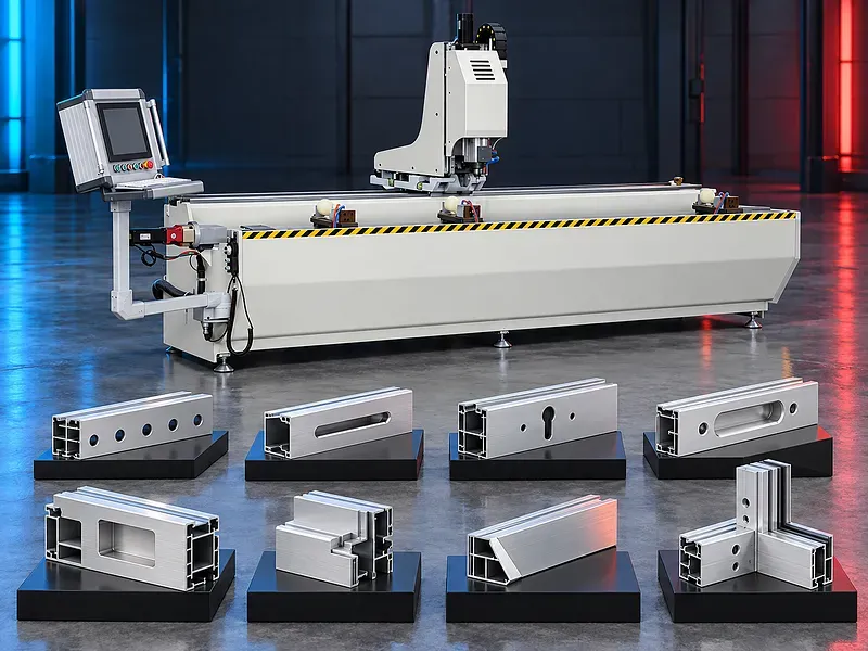
What the machine does
The machine positions an approved profile and executes programmed drilling milling grooving chamfering and related operations within its axis travel and tooling capability.
The result depends on accurate production data stable clamping tool selection spindle condition lubrication chip evacuation and inspection.
Three axis CNC movement
Coordinated axis movement positions the spindle and profile reference for each feature. Linear guides ball screws racks servo drives or other motion components depend on the supplied design.
Verify axis travels drive arrangement feedback reference sequence acceleration compensation and recovery after interruption.
Drilling holes and keyholes
The spindle can produce approved round holes elongated openings and keyhole features when the cutter path access and profile support are suitable.
Define diameter depth position breakthrough edge condition and the relationship between both sides of the profile.
Milling and grooving
Milling can create slots pockets channels drainage features hardware seats and simple contours within the approved travel and tool limits.
Feature depth width corner radius floor finish and wall condition should be specified on the part drawing.
Tapping and chamfering
Tapping and chamfering may be supported when the controller spindle tools and cycle provide the required synchronized operation. Thread form depth and material behavior must be verified.
Confirm whether tapping is rigid or uses a compensated holder and define tool breakage detection and inspection.
Window door and curtain wall profiles
The machine may prepare profiles for locks handles hinges drainage connectors facade brackets and other approved components.
Every profile family requires controlled orientation references program revision tooling and a first piece approval.
Materials and profile condition
Provide alloy temper extrusion geometry wall thickness surface finish coating protective film and dimensional tolerance. Composite profiles inserted reinforcement and internal chambers can affect tool access and cutting behavior.
Compatibility with aluminium wood composites light copper alloys or PVC requires approved trials and tooling rather than assumption.
Profile positioning and clamping
The profile should be supported and clamped without crushing chambers marking finishes or obstructing the tool path. Stationary or controlled positioning must preserve the machining reference.
Verify clamp locations pressure sensing repositioning logic usable length and rules for narrow flexible or asymmetrical sections.
Spindle tools and tool holding
Drills end mills slot cutters chamfer tools taps collets and holders must match the material feature spindle interface and approved speed.
Control tool length diameter projection balance wear resharpening and replacement through a documented setup.
Programming and operator interface
The operator interface supports program selection dimensions and cycle control according to the supplied functions. Accurate files and clear program names reduce setup errors.
Verify file formats offline programming simulation program storage backup user permissions language support and diagnostics.
Lubrication cooling and chip evacuation
Aluminium machining may require approved lubrication or cooling to control heat chip welding tool life and surface finish. Chips must leave pockets and hollow chambers without damaging the profile.
Confirm application method fluid compatibility extraction collection filtration and cleaning routine.
Accuracy and quality control
Acceptance should define feature position size depth thread quality angle edge finish burrs and assembly fit against approved drawings.
Inspect the first profile after setup tool change or program revision using calibrated measuring equipment and representative fixtures.
Safety and operator protection
The machine contains rotating tools moving axes automatic clamps and ejected chips. Guards monitored access emergency stops extraction and safe control functions should follow the approved risk assessment.
Safe procedures must cover loading programs tool changes trial machining unloading jam recovery cleaning and maintenance.
Installation and site readiness
Site preparation should confirm a level foundation electrical supply compressed air lubrication extraction network connection lighting profile handling and maintenance clearance.
Infeed outfeed and storage arrangements should support the longest profiles without blocking safe access.
Training maintenance and lifecycle support
Training should cover programs references clamping tooling quality checks safe recovery lubrication chip control and daily care.
Preventive maintenance should address spindle tools collets guides screws racks drives clamps sensors cables lubrication extraction guards and safety devices. Prepare approved spare parts and consumables.
How to select the correct machine
Start with profile drawings materials cross sections lengths all feature types access directions quantities batch mix tolerances software source surface requirements and downstream assembly.
Selection should be based on representative profile trials and a verified digital workflow rather than a general list of operations.
Technical information requiring verification
Verify profile length cross section and weight ranges axis travels spindle power speed torque and interface tool capacity feed speed clamping positioning accuracy cycle time lubrication extraction compressed air electrical load software interfaces dimensions and weight.
Supplier statements about imported motion components high precision and compatible materials require confirmation from an approved data sheet. Confirm installation commissioning training warranty service scope spare parts and acceptance tests.
Publishing status
This page describes the machine category and selection logic. Exact capacities speeds accuracy productivity materials functions options standards and commercial commitments require an approved data sheet and technical review before publication.
Questions we are asked
What is an aluminium CNC drilling and milling machine?
It is a programmed profile machining system that performs approved holes slots grooves pockets chamfers threads and related features through coordinated axis movement.
Which operations can it perform?
Functions may include drilling milling grooving tapping and chamfering when the spindle tools controller and machine travel support the required feature.
Can it process PVC or composite profiles?
Compatibility requires confirmation for the exact material profile construction tools speed and clamping. A sample trial is required.
How is the profile protected?
Suitable supports clamps contact pads lubrication and chip control should hold the profile without crushing chambers or damaging finished surfaces.
How is accuracy verified?
Inspect feature position dimensions depth threads edges and assembly fit on approved sample profiles using calibrated equipment.
What information is needed for selection?
Provide profile drawings materials cross sections lengths features access directions quantities tolerances software source surface requirements utilities and site layout.
Tell us the part you need to make
An engineer reads every request. Usually the same working day.
Related
- Aluminum Profile End Milling Machine End milling solutions for preparing aluminum profile ends for accurate fitting and assembly in suitable window, door and facade systems.
- Automatic Up Cut Mitre Saw for Aluminium and PVC An automatic up cut mitre saw uses a guarded blade that rises through the work area to cut approved aluminium and PVC profiles at straight or angled settings supported by the machine. Correct selection depends on profile material cross section length cut angles finished quality blade clamping feeding cooling extraction output target utilities and safety requirements.
- Double Head Mitre Saw for Aluminium and PVC A double head mitre saw cuts both ends of an approved aluminium or PVC profile to the required length and supported angles within one coordinated cycle. Correct selection depends on profile material cross section finished length angle combination cut quality blade configuration head positioning clamping support output utilities and safety requirements.