

WOOD SURFACE FINISHING
Wood Sanding and Polishing Machines for Flat and Profiled Surfaces
Wood sanding and polishing machines use selected abrasive units to smooth compatible flat shaped concave and convex surfaces before or between finishing stages. Correct selection depends on the workpiece geometry material coating condition stock removal finish standard abrasive system pressure feed method output dust extraction utilities and safety requirements.
The workpiece passes through or beneath abrasive brushes wheels belts discs or another approved finishing system. Flexible abrasive elements may follow selected profiles more closely than a rigid sanding surface but their reach and pressure vary across edges grooves recesses and raised details. A profiled sanding machine cannot guarantee a perfect finish on every shape. The actual process should be defined from representative parts and may combine several abrasive stages tool orientations manual touch up and inspection before coating or final assembly.
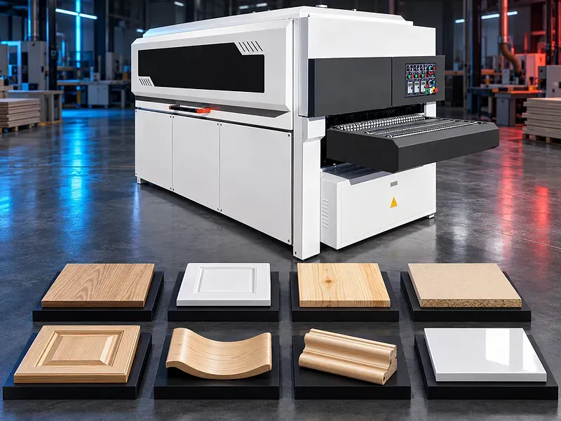
What a wood polishing machine does
The machine applies controlled abrasive contact to selected workpiece surfaces to remove fibres machining marks minor coating irregularities or sanding scratches and to prepare the surface for the next finishing stage.
In woodworking the term polishing may describe fine sanding or surface refinement. True gloss polishing of a cured coating may require different compounds pads speeds and process controls.
Flat and profiled surface applications
Potential work includes flat panels cabinet doors furniture fronts mouldings frame parts carved details routed panels solid wood components and selected coated pieces.
Suitability depends on whether the abrasive modules can reach the required surfaces while controlling edges corners recesses profiles and thin or delicate features.
Concave convex and detailed profiles
Flexible brushes or shaped sanding units may follow compatible concave convex and raised profiles. Contact pressure and abrasive action can change across the section and may leave some areas under sanded or over sanded.
Provide the profile drawing minimum radius groove depth feature height edge condition and areas that must retain sharp definition. Representative sample trials are essential.
Workpiece materials and condition
Potential materials may include compatible solid wood veneered panels medium density fibreboard routed boards primer coated parts and selected cured paint systems when approved for the abrasives feed and extraction system.
Species density grain moisture veneer thickness fibre direction filler primer coating hardness cure level contamination and previous machining marks affect abrasive choice removal and finish.
Process objective and surface standard
Define whether the task is calibration fibre removal denibbing sealer sanding primer sanding edge breaking scratch blending fine preparation or final coating refinement.
The acceptance standard should identify permitted scratches gloss variation profile definition edge rounding fibre lift burn through coating damage and the next process requirement.
Abrasive brushes and flexible wheels
Abrasive brushes or flexible wheels may use strips filaments flaps or other approved media to reach selected profiles. Their action depends on abrasive material grit density stiffness diameter projection speed direction and wear.
Verify module type abrasive construction grit range replacement method direction adjustment pressure limits dressing or cleaning method and approved use with coated surfaces.
Belts discs and sanding heads
Belts and discs may support controlled work on accessible flat or shaped areas when their contact system matches the workpiece. Oscillation floating heads or compliant pads may be included depending on the machine.
Confirm abrasive dimensions backing type grit range contact pad hardness oscillation travel head orientation edge behavior replacement access and tracking controls.
Module arrangement and tool orientation
Machines may combine transverse longitudinal angled rotating or oscillating units to approach surfaces from different directions. More modules do not automatically guarantee complete coverage.
Verify module quantity order orientation movement overlap working width height adjustment interference zones and whether a second pass or part rotation is required.
Feed system and workpiece control
Conveyors rollers belts pressure elements or fixtures move and restrain the part during sanding. Feed and hold down force should prevent movement without marking deforming or damaging the surface.
Confirm minimum part size permissible shape support area feed speed pressure adjustment slip detection treatment of warped parts and safe handling of narrow or light components.
Pressure speed and stock removal
Removal and finish depend on abrasive grit contact pressure tool speed feed speed number of passes timber or coating condition and module orientation.
Excessive pressure or dwell can round edges erase detail overheat the surface cut through veneer or coating and increase abrasive wear. Settings require sample validation.
Painted and coated workpieces
Painted parts should only be processed after the coating reaches the cure condition approved by its technical data. Different primers sealers lacquers and paint systems respond differently to heat pressure and abrasive action.
Confirm coating supplier instructions cure time dry film thickness allowable sanding method grit sequence dust classification and risk of loading smearing burn through or static.
Edge preservation and manual touch up
Flexible abrasives may soften sharp edges and raised details while deep recesses can receive less contact. Product design and finish requirements should define which edges may be broken and which details must remain sharp.
Some profiles may still require manual touch up specialist heads a separate machine or modified tooling. This should be included in cycle planning and quality approval.
Surface quality and inspection
Inspection may cover scratch pattern fibre lift smoothness profile consistency edge rounding gloss variation coating breakthrough dents pressure marks residual dust and readiness for the next finish stage.
The quality plan should define lighting reference samples tactile and visual criteria measurement where applicable first piece approval sampling abrasive change limits and handling of nonconforming parts.
Production workflow
Begin with an approved workpiece and finish specification material and coating check profile review abrasive sequence machine setup feed and pressure settings extraction settings and inspection method. Verify guards interlocks and emergency functions.
Run representative samples inspect all surfaces and apply only approved setting changes. Record the accepted abrasive sequence tool condition and touch up requirement before production.
Cycle time and production efficiency
Total cycle time includes part handling identification setup abrasive changes feeding sanding multiple passes part rotation dust removal inspection stacking and manual touch up.
No efficiency gain cycle time or production rate should be published without a timed trial using the real part geometry finish standard abrasive life staffing and quality plan.
Dust extraction and combustible risk
Wood and coating sanding can generate fine combustible dust and may release coating specific particles or vapours. Accumulation can affect finish mechanisms air quality housekeeping and fire or explosion risk.
Confirm extraction airflow pressure hood coverage ducting filtration dust classification grounding static control fire and explosion protection waste handling and compatibility with every approved material and coating.
Safety and operating risks
Risks include rotating or oscillating sanding units conveyors pressure devices entanglement crushing pinch points abrasive failure ejected parts dust fumes noise electrical energy pneumatic energy unexpected motion static and manual handling.
The machine requires approved guards interlocks emergency stops safe setup mode energy isolation controlled work holding extraction suitable abrasives loading zones training supervision and a documented risk assessment.
Installation and commissioning
Site planning should cover delivery access floor condition leveling anchoring service clearance part flow loading support electrical and air supplies extraction ducting dust collection fire controls lighting waste handling and maintenance access.
Commissioning should verify module alignment tool rotation movement feed and pressure systems extraction controls guards interlocks emergency functions representative samples operator training maintenance training documents and an agreed acceptance trial.
Maintenance and lifecycle support
Preventive maintenance should follow approved schedules for abrasive modules spindles bearings drives oscillation systems conveyors rollers pressure devices guides lubrication extraction sensors electrical controls guards interlocks and emergency devices.
Agree abrasive supply replacement and storage criteria brushes belts discs pads wear parts bearings belts filters cleaning tools lubricants calibration checks manuals training inspection records service responsibility and recommended spare parts.
How to select the correct machine
Provide workpiece drawings and samples material coating system cure condition incoming surface profile dimensions minimum radii target finish removal allowance quantities batch mix touch up limit and target output.
Also define abrasive preferences module orientation feed method changeover extraction utilities floor layout handling staffing maintenance capability upstream and downstream processes and acceptance tests.
Technical information to verify
Approved documents must confirm working width height and part size range module quantity type orientation travel abrasive dimensions and grit limits spindle or tool speeds feed speed pressure system and permissible workpiece shapes.
Extraction demand electrical and air requirements control functions dimensions weight floor loading noise basis guards safety functions standard equipment options abrasives manuals training warranty service and acceptance method also require confirmation.
Limitations and publishing status
The supplied description does not verify perfect profile sanding material or coating compatibility module arrangement working dimensions speed accuracy finish efficiency output extraction or safety configuration.
Publication requires the approved exact datasheet machine layout abrasive and module list electrical and pneumatic drawings extraction and safety documents coating compatibility evidence representative sample results approved image technical review staging review and final content approval.
Technical review and next step
Send workpiece drawings and samples material and coating data profile dimensions finish requirement removal allowance quantities output utilities and factory layout for technical review.
The review should define the suitable modules abrasive sequence feed pressure extraction inspection touch up acceptance trial installation training maintenance consumables and spare parts scope.
Questions we are asked
What is a wood polishing machine?
It is a surface finishing machine that uses selected abrasive units to sand smooth or refine compatible flat and profiled wood or coated workpieces.
Can it sand concave and convex surfaces?
Flexible abrasive modules may reach selected concave and convex profiles but coverage depends on radius depth orientation pressure and workpiece geometry. Sample trials are required.
Can it process painted parts?
Only when the coating is sufficiently cured and approved for the selected abrasive method pressure speed extraction and safety controls.
Does it eliminate manual sanding?
Some manual touch up may remain on deep recesses sharp details edges or areas outside the machine reach. The actual share must be verified by sample parts.
What information is needed for selection?
Provide workpiece drawings and samples material and coating data profile dimensions finish standard removal allowance quantities output utilities and factory layout.
Tell us the part you need to make
An engineer reads every request. Usually the same working day.
Related
- CNC WOOD ROUTER CNC routing solutions for cutting, drilling, engraving and machining suitable wood panels and furniture components.
- CNC ROUTER WITH ROTARY A CNC router equipped with a rotary attachment or axis for machining suitable cylindrical and shaped workpieces. Selection depends on the part geometry, material, dimensions, required operations, accuracy, and production volume.
- Automatic Edge Banding Machines Automatic edge banding machines apply and finish compatible edge material on straight panel edges through a controlled production sequence. Correct selection depends on the panel material dimensions edge tape adhesive production volume finish requirement installed processing units utilities and extraction system.