

SOLID WOOD FACE AND EDGE PREPARATION
Surface Planer and Jointer Machines
Surface planer jointers prepare compatible timber by creating a flat reference face and a straight edge at the required relationship to that face. Correct selection depends on timber species moisture dimensions initial distortion working width table geometry fence cutterhead tooling extraction tolerance and production needs
During face jointing the workpiece passes over the cutterhead from the infeed table to the outfeed table so high points are removed until a usable reference face is produced. During edge jointing the prepared face runs against the fence while the adjacent edge is straightened. A jointer does not normally set the opposite face to a finished parallel thickness. If the selected machine also includes a thicknesser function this must be confirmed as a separate approved configuration with its own capacity setup and safety requirements.
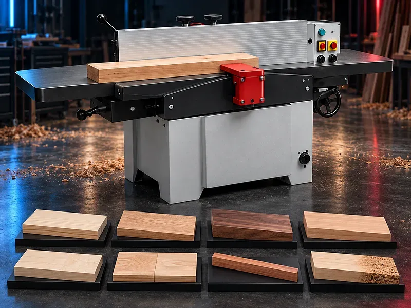
What a surface planer jointer does
The machine removes controlled material from a compatible timber face or edge as the workpiece is guided across a rotating cutterhead. The tables and fence provide references for flatness straightness and the required edge relationship.
The result depends on stock condition table alignment cutter sharpness depth of cut grain direction support feeding technique extraction and the actual machine condition.
Jointer and thicknesser are different operations
A jointer or surface planer establishes a flat face and straight edge. A thicknesser references a prepared face to machine the opposite face parallel at a controlled thickness.
Some machines combine both functions through a changeover arrangement but combination capability must be verified. The page should not promise thickness control unless the selected machine includes an approved thicknesser unit.
Stock inspection and preparation
Inspect timber for metal stones loose knots severe splits rot dirt coating and other hazards before machining. Confirm moisture dimensions grain defects and the amount of bow cup or twist.
Stock that is too short thin narrow unstable or damaged may not be safe to joint. Minimum workpiece limits and required push devices must follow approved instructions.
Face jointing
Face jointing aims to create one flat reference surface by removing high points over successive controlled passes. The operator should maintain stable contact with the outfeed table as the cut progresses.
The process plan should identify the reference face support points pass sequence removal allowance and acceptance method. Excessive depth of cut can increase load tear out and handling risk.
Edge jointing
After a reference face is prepared it can run against the fence while an adjacent edge is straightened. The fence relationship determines whether the edge is square or set to an approved angle.
A straight jointing result depends on fence alignment table condition workpiece pressure cutter setup and consistent support. A test piece should verify the edge before production.
Infeed and outfeed tables
The infeed table is set below the cutter reference by the required depth of cut. The outfeed table supports the newly machined surface and should align correctly with the cutter path according to the machine design.
Table length flatness coplanarity adjustment locks surface condition and extensions affect support and result. Exact tolerances and alignment procedures require approved documentation.
Fence and angle setting
The fence guides the reference face during edge jointing and may be adjustable for square or angled work when supported. Fence height length rigidity flatness locking and alignment influence edge accuracy.
Confirm angle range stops scale or digital indication adjustment method and calibration. The selected fence position must also allow the cutter guard to cover the unused cutterhead area.
Cutterhead and knives
Possible cutter systems may use straight knives segmented inserts helical heads or another approved arrangement. Knife material geometry projection balance sharpness and setting affect cutting load finish vibration noise and service life.
Confirm cutterhead width diameter speed knife quantity knife type setting method replacement procedure permissible projection balance requirement and approved tooling sources.
Cutterhead guard
An approved guard should cover the unused portion of the cutterhead while allowing the workpiece to pass. Guard movement return action adjustment and condition are central to safe operation.
The exact bridge guard pork chop guard or other protection system depends on the machine design. It should be inspected and tested before use and after adjustment.
Depth of cut and pass planning
Depth of cut is the amount removed during a pass. The permitted setting depends on workpiece width timber density moisture cutter condition motor load grain and desired surface.
Warped stock may require several light passes. The operator should avoid forcing unstable material flat against the table because it may recover after machining.
Grain direction and surface finish
Feeding with favorable grain direction can reduce tear out while reversing or changing grain may require a lighter cut slower controlled feed or another process. Knots and figured grain remain more difficult.
Trial pieces should establish settings that control tear out ripple marks glazing burns and dimensional variation without exceeding approved machine limits.
Workpiece support and feeding
Long or heavy parts need stable infeed and outfeed support at the correct height. Push blocks push pads support stands or additional trained operators may be required according to part size and risk assessment.
Hands should remain at approved safe positions and should not pass over an exposed cutterhead. Feeding should be controlled without reaching pulling from unsafe positions or losing reference contact.
Common machining defects
Potential defects include taper convex or concave surfaces edge not square tear out knife marks ripple steps at the table transition burning chatter scratches and remaining twist.
Diagnosis should check stock support table alignment fence cutter setting knife condition depth feed direction pressure and technique before corrective adjustment.
Dust and chip extraction
Jointing produces chips and dust that can affect visibility finish cutter cooling table movement fire risk and operator exposure. Extraction should collect waste close to the cutter enclosure.
Required airflow pressure duct size connection points filtration waste handling dust classification fire controls and housekeeping depend on timber removal and local requirements.
Production workflow
Begin with approved part dimensions timber identification moisture and defect inspection reference face decision removal allowance grain review cutter and fence settings and inspection method. Check tables guards extraction emergency functions and tool condition.
Run a sample establish the reference face joint the edge measure flatness straightness and squareness apply approved corrections then process the batch with regular checks and material traceability.
Quality and inspection
Inspection may cover face flatness edge straightness squareness or specified angle twist bow surface roughness knife marks ripple tear out burn marks chatter scratches and allowance for thicknessing sanding or further machining.
The quality plan should define datums tolerances gauges sampling calibration first piece approval knife change criteria correction limits and handling of nonconforming parts.
Potential applications
Potential applications include compatible furniture stock cabinet parts door and window components frames table components stair parts flooring blanks moulding blanks and general solid wood preparation.
Suitability depends on timber condition part dimensions reference requirements tolerance visible surface downstream thicknessing sawing profiling jointing sanding coating and assembly.
How to choose the correct machine
Provide timber species moisture density incoming dimensions maximum width part length distortion removal allowance required reference faces edge angle tolerance quantity batch mix finish and target output.
Also define cutter preference table and fence needs thicknesser combination requirement extraction electrical supply floor space support equipment staffing maintenance capability noise controls and acceptance tests.
Technical information to verify
Approved documents must confirm machine type working width table length infeed and outfeed dimensions maximum depth of cut fence size angle range cutterhead diameter speed knife system table adjustment minimum workpiece dimensions and any thicknesser function.
Motor power electrical load extraction port and airflow requirements braking dimensions weight floor loading foundation noise basis cutter guard emergency stop controls standard equipment options tools documents training warranty service and acceptance method also require confirmation.
Safety and operating risks
Risks include cutter contact kickback ejected knots or fragments moving timber sharp edges chips dust noise electrical energy stored mechanical energy unstable workpieces heavy handling and knife changes.
The machine requires approved cutter guards emergency stops braking push blocks safe hand positions support methods extraction isolation knife change tools lifting controls training supervision and a documented risk assessment.
Installation and commissioning
Site preparation should cover delivery access level floor anchoring infeed and outfeed clearance timber storage support tables electrical supply extraction ducting dust collection fire controls lighting and maintenance access.
Commissioning should verify level table coplanarity cutter and outfeed relationship fence squareness guard action depth adjustment extraction controls safety functions stopping behavior sample cuts operator training maintenance training documents and an agreed acceptance trial.
Maintenance and lifecycle support
Preventive maintenance should follow approved schedules for cutterheads knives inserts bearings belts tables slides locks fence adjustments guards brakes extraction sensors controls fasteners lubrication and emergency devices.
Agree sharpening and replacement criteria knives inserts bearings belts guards springs filters lubricants setting gauges calibration tools technical documents training inspection records and service responsibility for the selected machine.
Limitations and publishing status
The supplied description does not verify jointer or combination configuration working width table geometry thickness control motor power precision efficiency construction result quality material range workpiece capacity or suitability for professional production.
Publication requires the exact approved datasheet machine configuration capacity and table data cutter and guard information extraction and safety instructions sample test results approved image technical review staging review and final content approval.
Technical review and next step
Send timber samples material data incoming dimensions distortion removal allowance required faces and edges quantities tolerances finish extraction utilities and factory layout for technical review.
The review should define the suitable machine type cutter system table and fence configuration guarding support extraction inspection acceptance trial installation training maintenance tooling and spare parts scope.
Questions we are asked
What is a surface planer jointer?
It is a woodworking machine used to create a flat reference face and a straight edge on compatible timber before further sizing and machining.
Is a jointer the same as a thicknesser?
No. A jointer establishes a flat face and straight edge while a thicknesser machines the opposite face parallel to a prepared reference at a controlled thickness.
Can the machine process hardwood and softwood?
Only when the approved capacity cutter tooling extraction and settings support the exact species moisture dimensions and required finish.
What affects jointing quality?
Stock condition table and fence alignment cutter sharpness knife setting depth of cut grain direction support feeding technique extraction and maintenance all affect the result.
What information is needed for selection?
Provide timber species moisture dimensions distortion required reference faces edge angle tolerance quantities finish extraction utilities and factory layout.
Tell us the part you need to make
An engineer reads every request. Usually the same working day.
Related
- CNC WOOD ROUTER CNC routing solutions for cutting, drilling, engraving and machining suitable wood panels and furniture components.
- CNC ROUTER WITH ROTARY A CNC router equipped with a rotary attachment or axis for machining suitable cylindrical and shaped workpieces. Selection depends on the part geometry, material, dimensions, required operations, accuracy, and production volume.
- Automatic Edge Banding Machines Automatic edge banding machines apply and finish compatible edge material on straight panel edges through a controlled production sequence. Correct selection depends on the panel material dimensions edge tape adhesive production volume finish requirement installed processing units utilities and extraction system.