

AUTOMATED DOOR FRAME AND FURNITURE MACHINING
CNC Combined Milling and Cutting Machine
A CNC combined milling and cutting machine performs coordinated recess machining and angled cutting on door frame and furniture components in one automated cycle. Correct selection depends on workpiece material profile dimensions machining geometry tool requirements finished quality output target clamping method extraction utilities and safety conditions.
The machine is designed to combine operations that may otherwise require separate setups. It can position and clamp the component before machining parallel recesses and approved angled cuts on the required sides according to the programmed cycle. Automatic clamping and release can reduce repeated manual handling and support consistent production. The exact machining functions workpiece range tooling and cycle sequence must be confirmed from the approved technical documentation for the offered equipment.
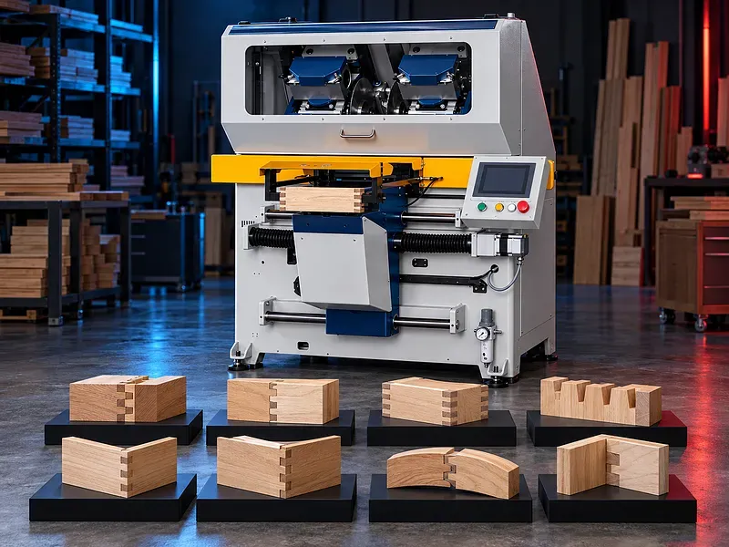
What the machine does
The machine combines controlled milling and cutting stations to process prepared wood or approved wood based components. The controller sequences positioning clamping machining return and release according to the selected program.Combining the operations can reduce transfers between machines and preserve a common reference when the workpiece tooling and program are correctly prepared.Typical production workflow
The operator selects the approved program checks the tools and loads the prepared component against the defined references. The machine secures the workpiece performs the programmed operations and releases it after the cycle reaches a safe completion state.Loading orientation part identification and completed part segregation should be defined to prevent mirrored features mixed components or repeated machining.Parallel recess milling
Milling units can create parallel recesses slots seats or related features when supported by the approved machine configuration and tooling. Feature width depth spacing and position depend on the drawing tool geometry spindle setup and reference surfaces.Confirm whether the required features are machined simultaneously or sequentially and define the permitted breakout tear out and edge condition.Angled cutting
The cutting station can produce approved angled end cuts for door frame or furniture components when its adjustment range blade and clamping arrangement match the part. The angle should be programmed or set according to the verified configuration.
Cut quality depends on blade selection sharpness rotation direction feed stability workpiece support and material condition.Door frame applications
The machine may support production of door frame members that require repeated recesses and angled ends. Each frame family should have a controlled drawing program tooling setup and inspection sample.Confirm jamb head and related component orientation dimensions joints hardware locations and assembly allowance before approving the machining cycle.Furniture component applications
Approved furniture rails stiles frame parts and similar components may be processed when their profiles dimensions and materials fit the machine envelope. Curved flexible irregular or already finished components may require a different fixture or process.A sample machining trial should confirm support marking breakout and dimensional stability for every new product family.Materials and workpiece condition
Provide the material type solid wood species engineered board structure coating moisture content grain direction density profile and dimensional tolerance. Knots voids laminations surface films and internal fasteners can affect safety and finish.Workpieces should be straight clean and within the approved size and moisture range. Material suitability must not be assumed from the product name alone.CNC control and programs
The control panel supports selection and management of machining cycles according to the supplied functions. Stored programs can reduce setup variation when names revisions access permissions and backups are managed correctly.Verify programmable dimensions axes parameter limits language support program capacity backup method diagnostics and recovery after an interrupted cycle.Automatic clamping and release
Clamps hold the component against defined references before the tools enter the work area. Release should occur only after the machining units return to their approved safe positions and the control sequence permits unloading.Confirm clamp locations pressure adjustment sensing and compatibility with delicate hollow narrow or profiled parts. Excessive pressure may mark or deform the workpiece while insufficient pressure can allow movement.Tooling and setup
Cutters saw blades collets holders spacers and fixtures must match the approved material feature geometry spindle interface and speed range. Tool condition and projection influence vibration finish and dimensional accuracy.Create a controlled setup sheet for each product including tools references offsets clamping points program revision and first piece inspection.Machining quality and inspection
Acceptance should define feature position width depth angle squareness edge finish breakout and part length according to the finished product drawing. The first piece should be inspected before a production batch continues.Use calibrated gauges templates or measuring tools suited to the tolerance. Record tool changes corrections and rejected parts when traceability is required.Dust extraction and housekeeping
Milling and cutting generate chips and fine dust that can affect finish machine reliability visibility and fire risk. The extraction system must provide the approved airflow and connection arrangement for all active stations.Ducts collection equipment filters and housekeeping frequency should suit the processed material and production duty. Deposits must not be allowed to accumulate around motors tools sensors or electrical cabinets.Safety and operator protection
The machine contains rotating cutters a saw blade automatic clamps moving axes and ejected chips. Guards monitored access emergency stops extraction and safe control functions should be provided according to the approved risk assessment.Safe procedures must cover loading setup tool changes trial runs production unloading jam recovery cleaning and maintenance. Reaching into the machining zone before verified isolation is prohibited.Installation and site readiness
Site preparation should confirm floor condition working space electrical supply compressed air when required extraction connection lighting material flow and safe maintenance access. Incoming and finished part storage should not obstruct the operator zone.Installation should include machine leveling service connections tool installation reference checks safety tests and trial machining with approved samples.Training maintenance and lifecycle support
Training should cover programs references clamping tooling inspection safe recovery dust control and daily checks. Operators should understand how incorrect loading tool selection or part orientation affects both quality and safety.Preventive maintenance should address cutters blades holders clamps guides bearings drives lubrication sensors extraction hoses and safety devices. Prepare an approved spare parts and consumables list for the final configuration.How to select the correct machine
Start with component drawings material types minimum and maximum dimensions recess details cutting angles quantities batch sizes tolerances and finished surface requirements. Then define the required functions automation handling extraction utilities and acceptance sample.Selection should be based on the complete product family and verified trials rather than one sample part or an unsupported productivity claim.Technical information requiring verification
Verify the workpiece length width thickness and profile ranges. Also verify spindle count power and speed tool diameters cutting angle range axes feed speed clamping system positioning accuracy cycle time extraction demand compressed air electrical load dimensions and weight.Confirm included tooling guarding control functions installation commissioning training warranty service scope spare parts and the agreed factory and site acceptance tests.Publishing status
This page describes the machine category and selection logic. Exact capacities speeds accuracy productivity features options standards and commercial commitments require an approved data sheet and technical review before publication.Questions we are asked
What is a combined milling and cutting machine?
It is a CNC controlled machine that combines approved recess milling and angled cutting operations within one coordinated cycle for suitable door frame and furniture components.
Can it machine both sides of a component?
Machining on both sides may be supported when the exact machine configuration tooling and program provide that function. The required features must be confirmed from the drawing.
Which materials can be processed?
Compatibility depends on the approved solid wood or engineered wood material dimensions moisture profile coating and tooling. A sample trial is required for confirmation.
Does the machine clamp parts automatically?
Automatic clamping and release may be part of the operating cycle. Clamp positions pressure sensing and safe release sequence must be verified for the offered configuration.
How is machining quality checked?
The first piece is measured against the approved drawing for recess dimensions angle part length edge finish and breakout before batch production continues.
What information is needed for selection?
Provide part drawings materials dimensions recess details cutting angles quantities tolerances surface finish requirements extraction utilities and site space.
What should be included in acceptance?
Acceptance should verify guards controls references clamping tools programmed cycles finished dimensions surface quality extraction and safe recovery using approved sample parts.
Tell us the part you need to make
An engineer reads every request. Usually the same working day.
Related
- CNC WOOD ROUTER CNC routing solutions for cutting, drilling, engraving and machining suitable wood panels and furniture components.
- CNC ROUTER WITH ROTARY A CNC router equipped with a rotary attachment or axis for machining suitable cylindrical and shaped workpieces. Selection depends on the part geometry, material, dimensions, required operations, accuracy, and production volume.
- Automatic Edge Banding Machines Automatic edge banding machines apply and finish compatible edge material on straight panel edges through a controlled production sequence. Correct selection depends on the panel material dimensions edge tape adhesive production volume finish requirement installed processing units utilities and extraction system.