

CNC WOOD TURNING SOLUTIONS
CNC Wood Lathes for Furniture and Decorative Components
CNC wood lathes shape compatible timber blanks into repeatable turned components such as furniture legs balusters posts and selected decorative parts. Correct machine selection depends on the finished drawing timber condition blank dimensions profile complexity tooling support method tolerance output extraction utilities and safety requirements.
A CNC wood lathe rotates a securely held timber blank while programmed cutting tools remove material to form approved diameters tapers curves grooves and transitions. The operator prepares the blank selects verified tooling loads an approved program completes setup checks and starts a guarded machining cycle. Some configurations may add milling carving sanding copying automatic loading or multiple cutting stations. These are optional machine capabilities and should only be published after the exact configuration control functions tooling and safety provisions are confirmed from approved technical documents.
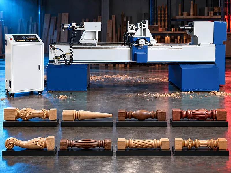
What a CNC wood lathe does
The machine turns a compatible timber blank around its longitudinal axis while controlled tools generate the programmed external profile. Depending on the verified configuration it may produce straight cylindrical tapered convex concave stepped grooved or blended surfaces.
CNC control supports repeatable programmed movement but does not by itself prove accuracy finish cycle time or compatibility with every timber species and product shape.
Typical finished components
Potential products include table legs chair legs sofa feet stool legs stair spindles balusters newel posts handrail posts bed posts decorative columns lamp bodies handles tool grips sporting goods and selected turned craft components.
Bowls cups vases pens and hollow products may require different chucking internal turning axes or specialist tooling. Their suitability must be confirmed separately rather than assumed from external profile turning capability.
Product drawing and profile definition
Provide a dimensioned drawing or approved digital profile defining overall length finished diameters tapers radii curves shoulders grooves transitions end details and datum positions. Decorative patterns should be supplied in a compatible approved file format when the control supports them.
The drawing should also identify visible surfaces grain orientation areas requiring later machining sanding or assembly and the permitted variation between matching parts.
Timber and blank condition
Potential materials may include compatible solid hardwood and softwood species and selected laminated blanks when approved for the machine tooling holding method and extraction system.
Species density moisture content grain direction knots checks adhesive lines coatings metal contamination blank straightness balance and dimensional allowance affect cutting load vibration tool life tear out finish and final stability.
Blank dimensions and preparation
Confirm minimum and maximum blank length diameter or cross section finished profile envelope and machining allowance. Oversized unbalanced cracked or poorly prepared blanks can increase vibration and risk during rotation.
Blank preparation may include sizing end facing center marking drilling mounting features moisture conditioning inspection and rejection criteria before loading.
Work holding and support
The blank may be held between approved centers or by a verified chuck faceplate mandrel collet fixture or another method suited to the product. Long or slender workpieces may require a tailstock steady rest follower or intermediate support.
Confirm clamping force drive engagement support positions tool clearance permissible overhang and safe retention throughout acceleration cutting deceleration and unloading.
Spindle and drive system
The spindle and drive rotate the blank within the limits of the selected machine. Suitable speed depends on blank diameter balance timber condition tooling cutting method profile and approved safety limits.
Verify spindle quantity motor power speed range speed control torque chuck or center interface braking load limits bearing arrangement runout basis and protection against unintended restart.
Cutting tools and tool stations
Possible tooling may include turning cutters profile knives router tools sanding heads or another approved system. Tool geometry material projection setting and cutting direction should suit the timber profile spindle rotation and required finish.
Confirm tool station quantity toolholder interface adjustment replacement method sharpening policy offsets guarding extraction access collision zones and approved tool suppliers for the exact configuration.
CNC axes programming and recipes
Programmed axes may coordinate tool position and feed along the workpiece to generate the selected profile. The control may use numerical dimensions templates imported profiles or stored recipes depending on the installed software.
Confirm axis quantity travels feed limits interpolation functions interface language file compatibility recipe capacity tool compensation simulation permissions backup method alarms diagnostics and program change control.
Milling and decorative carving options
Milling or carving can add flutes spirals slots facets relief details or selected decorative patterns only when a powered tool spindle suitable axes control functions clamping and guarding are included.
Verify powered tool quantity power speed orientation travel supported operations file preparation tool library indexing method cycle sequence extraction and achievable detail through an approved sample trial.
Sanding and finishing considerations
Turning can leave tool marks fibers or local tear out that may require sanding or another finishing process. An integrated sanding option must be confirmed and matched to the profile timber dust system and finish requirement.
Define the acceptable surface standard sanding sequence abrasive grades manual finishing allowance coating preparation and inspection method before promising a finished surface directly from the machine.
Production workflow
Production begins with an approved drawing timber identification moisture check blank inspection program tooling list work holding plan extraction settings and quality method. Guards interlocks supports tools centers and emergency functions should be checked before the cycle.
A sample part should be machined and inspected for dimensions profile symmetry surface condition end details and assembly fit. Approved corrections are then recorded before controlled batch production begins.
Quality and inspection
Inspection may cover overall length diameters taper radii groove positions concentricity runout symmetry profile comparison surface finish burning tear out cracks tool marks and fit with mating components.
The quality plan should define datums tolerances gauges templates sampling frequency first piece approval tool wear compensation correction limits traceability and control of nonconforming parts.
Cycle time and production capacity
Total cycle time includes loading referencing clamping acceleration machining any milling carving or sanding deceleration inspection unloading cleaning and changeover. Profile complexity material behavior and tool life can change output significantly.
No production rate or minutes per part should be published without a timed trial using the actual drawing timber blank tooling finish requirement staffing and inspection plan.
Dust chip and fire risk control
Wood turning generates chips fine dust and offcuts near rotating work and cutting tools. Poor collection can affect visibility finish tool load mechanisms air quality and fire risk.
Confirm hood design extraction ports airflow pressure duct size filtration waste handling dust classification grounding spark and fire controls housekeeping procedure and compatibility with every installed operation.
Safety and operating risks
Risks include rotating blanks chucks centers cutters powered tools axes entanglement ejected timber tool breakage kickback crushing pinch points dust noise electrical energy compressed air unexpected automatic motion program errors and manual handling.
The machine requires approved enclosures guards interlocks emergency stops safe setup mode energy isolation secure work holding correct speed selection extraction tool verification loading zones operator training supervision and a documented risk assessment.
Installation and commissioning
Site preparation should cover delivery access floor condition anchoring service clearance material flow blank storage work support electrical supply compressed air when required extraction ducting dust collection fire controls lighting and maintenance access.
Commissioning should verify level spindle and center alignment axis calibration tool data supports work holding extraction programs guards interlocks emergency functions sample parts operator training maintenance training documents and an agreed acceptance trial.
Maintenance and lifecycle support
Preventive maintenance should follow approved schedules for spindle bearings drives guideways screws servos toolholders cutters chucks centers tailstock supports lubrication extraction sensors electrical cabinet guards interlocks and emergency devices.
Agree tool sharpening and replacement criteria wear parts bearings belts seals sensors filters lubricants calibration tools software backups recipes technical manuals inspection records training service responsibility and recommended spare parts.
How to select the correct configuration
Provide finished product drawings timber species moisture blank dimensions profiles quantities batch sizes tolerance surface requirement secondary operations target output and available staffing.
Also define required turning axes milling carving sanding loading and support options tooling extraction utilities floor space material handling maintenance capability and acceptance criteria.
Technical information to verify
Approved documents must confirm workpiece length and diameter ranges blank weight profile limits spindle quantity power speed and interface axis quantity travel feed rates tool stations powered tool options work holding supports and loading arrangement.
Control software file formats accuracy and repeatability basis extraction demand electrical and air requirements dimensions weight floor loading noise basis guards safety functions standard equipment options tooling manuals training warranty service and acceptance method also require confirmation.
Limitations and publishing status
The supplied description does not verify ease of use machining time fine finish compatible timber list product capacity milling carving support exact accuracy production efficiency or suitability for bowls hollow products and every decorative shape.
Publication requires the exact approved datasheet machine drawing control and axis list spindle tooling and work holding data extraction and safety instructions actual sample results approved image technical review staging review and final content approval.
Technical review and next step
Send the finished part drawing blank dimensions timber data quantities tolerance surface requirement tooling preference desired optional operations utilities and factory layout for technical review.
The review should define the suitable configuration tools work holding supports program preparation extraction inspection acceptance trial installation training maintenance consumables and spare parts scope.
Questions we are asked
What is a CNC wood lathe?
It is a woodworking machine that rotates a secured timber blank while programmed cutting tools form an approved external profile.
Which products can it make?
Potential products include compatible furniture legs balusters posts handles and decorative turned components. The exact range depends on capacity tooling work holding axes and software.
Can it mill or carve decorative patterns?
Only configurations equipped with verified powered tooling suitable axes control functions clamping extraction and guarding can perform supported milling or carving operations.
Which wood species can be processed?
Suitability depends on species density moisture grain defects blank condition tooling and extraction. Each material should be approved through technical review and a sample trial.
What information is needed for machine selection?
Provide the finished drawing timber data blank dimensions quantities tolerances finish optional operations target output utilities and factory layout.
Tell us the part you need to make
An engineer reads every request. Usually the same working day.
Related
- CNC WOOD ROUTER CNC routing solutions for cutting, drilling, engraving and machining suitable wood panels and furniture components.
- CNC ROUTER WITH ROTARY A CNC router equipped with a rotary attachment or axis for machining suitable cylindrical and shaped workpieces. Selection depends on the part geometry, material, dimensions, required operations, accuracy, and production volume.
- Automatic Edge Banding Machines Automatic edge banding machines apply and finish compatible edge material on straight panel edges through a controlled production sequence. Correct selection depends on the panel material dimensions edge tape adhesive production volume finish requirement installed processing units utilities and extraction system.