

CNC WOOD JOINERY MACHINING
CNC Tenoning Machines for Wood Components
CNC tenoning machines form compatible tenons and shoulders on timber components through programmed cutter and workpiece movements. Correct selection depends on the joint drawing timber workpiece dimensions tenon geometry references tooling axes clamping angle requirements tolerance production mix extraction utilities and safety controls.
The operator references and clamps the workpiece enters or selects approved parameters and starts a guarded machining cycle. The CNC may coordinate cutterhead position tenon dimensions angle and motion sequence according to the installed axes and software. Potential configurations may use one or two worktables and cutter movement in horizontal vertical or inclined directions. These features and any external adjustment method must be confirmed from the approved machine drawing control list and operating manual
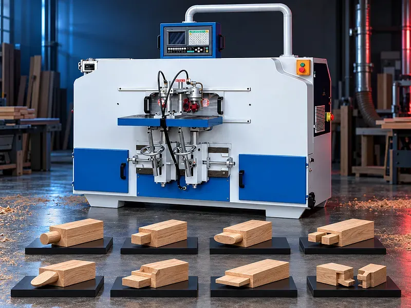
What a CNC tenoner does
The machine removes material from the end of a compatible timber component to create a tenon and shoulders that fit an approved mating mortise or joint. Programmed motion can control selected dimensions and profiles within the installed machine capability.
The tenoner should be selected from the complete joint and product requirements. CNC control alone does not prove precision cycle time or compatibility with every tenon shape.
Tenon and joint geometry
The joint drawing should define tenon length width thickness shoulder positions corner radii haunches cheeks faces angle offsets and relationship to the workpiece datums. The mating mortise defines the required fit and adhesive allowance.
Provide assembly drawings tolerance stack joint strength requirements and an approved sample where available. Moisture movement and downstream assembly should be considered.
Potential workpiece materials
Potential work may include compatible hardwood softwood laminated timber and selected engineered wood components when approved for the cutter clamping and extraction system.
Species density moisture grain knots adhesive lines coating dimensions and internal contaminants affect cutting load tool life breakout surface quality and joint performance.
Workpiece reference and positioning
Stable datums are required for part length face edge end and joint center. Stops fences tables clamps or programmed position systems may establish these references according to the machine.
The setup should control part orientation end allowance left and right hand parts accumulated dimensional error and the relationship between the tenon and product references.
Clamping and work holding
The workpiece should be held securely against approved references before cutter movement. Clamps should resist cutting forces without crushing marking twisting or moving the timber.
Confirm clamp type quantity position pressure adjustment sensors support for narrow short curved or angled parts and the safe behavior after air or power loss.
Single and double worktable arrangements
A machine may use one worktable or two alternating worktables to support loading and machining according to the selected design. A double table does not automatically mean both tables are machined at the same time.
Confirm table quantity operating sequence loading zone guarding interlocks reference repeatability permissible part sizes and operator access.
Cutterhead and tooling
Possible tooling may include tenoning heads cutter blocks router bits end mills saws or another approved system depending on the desired joint. Tool diameter width profile projection mass speed and rotation should suit the timber and spindle.
The supplied reference to a welded cutterhead requires verification. Confirm cutter construction replaceable parts balancing mounting torque tool limits sharpening setting gauges and approved sources.
Machine axes and cutter movement
CNC axes may position the cutterhead or worktable horizontally vertically and at selected inclinations when supported. Axis motion can generate cheeks shoulders offsets radii haunches and selected shaped tenons according to the installed software and tooling.
Confirm axis quantity travels feed rates acceleration position feedback repeatability basis collision zones lubrication covers calibration and service access.
Tenon depth and dimensional adjustment
Tenon length or machining depth may be adjusted through parameters external controls handwheels or a verified mechanical setting depending on the design. Adjustment should remain within tool projection and guard limits.
Confirm adjustment method resolution locking calibration compensation for cutter diameter and wear and whether setup can be completed without opening a protective enclosure.
Angled tenons and tilting table
A tilting worktable or cutter axis may support selected angled tenons when included. The usable angle depends on clamping surfaces cutter reach part clearance joint geometry and collision limits.
Confirm angle range stops indication locking calibration accuracy basis capacity reduction and safe guard coverage. The supplied angle range requires approved data.
CNC parameters and recipes
A parameter driven control may allow the operator to enter selected tenon dimensions choose a machining mode and store approved recipes. The controller translates the data into motion only within the programmed functions and machine limits.
Confirm interface language parameter fields recipe capacity tool data permissions simulation or preview alarm handling diagnostics network options backup procedure and change control.
Electrical control and protection
The electrical system should match the site supply and protect motors drives controls and safety circuits according to the approved design. A transformer or power conditioning device may be installed when specified.
Confirm input voltage frequency load short circuit and overload protection transformer rating control voltage grounding cabinet cooling component list fault logging and response to supply variation.
Chip evacuation and extraction
Tenoning can produce chips dust and offcuts around fast moving cutters. Poor removal may affect visibility cooling surface quality tool load mechanisms fire risk and operator exposure.
Confirm hoods extraction ports airflow pressure duct size filtration waste handling dust classification fire controls and cleaning procedures for every tool and workpiece orientation.
Production workflow
Begin with approved product and joint drawings timber identification moisture check reference plan tooling list CNC program clamping setup extraction settings and inspection method. Check guards interlocks sensors and emergency functions.
Run a sample tenon inspect dimensions shoulders angle profile surface and fit with the mating mortise apply approved corrections lock the recipe then release production with regular checks and tool monitoring.
Quality and inspection
Inspection may cover tenon length width thickness position shoulders squareness angle symmetry radii haunches breakout tear out burning tool marks cracks surface condition and fit with the mating joint.
The quality plan should define datums tolerances gauges fixtures sampling calibration first piece approval tool wear compensation change criteria correction limits and handling of nonconforming parts.
Potential applications
Potential applications include compatible door rails and stiles table and chair components furniture frames window parts bed frames cabinet frames and selected structural or decorative joinery components.
Suitability depends on part cross section timber joint design visible surfaces tolerance production mix handling downstream assembly adhesive process and required joint performance.
Cycle time and production planning
Programmed settings and multiple worktables may reduce selected manual adjustments or loading delays, but total cycle time includes handling referencing clamping machining chip clearing inspection unloading and changeover.
No single person efficiency speed or output claim should be published without a timed trial using the real part tool life staffing and quality plan.
How to choose the correct machine
Provide product joint and assembly drawings timber species moisture incoming dimensions tenon types dimensions positions angles quantities batch mix tolerance finish joint fit and target output.
Also define required axes table quantity cutterhead and tools clamping CNC parameter needs extraction compressed air electrical supply floor space handling staffing maintenance capability and acceptance tests.
Technical information to verify
Approved documents must confirm workpiece length width and thickness ranges tenon dimension range supported profiles table quantity and size tilt range axes quantity travels feed rates position feedback and programming functions.
Cutterhead construction spindle quantity power speed tool capacity clamps air demand extraction ports electrical load transformer controls software accuracy and repeatability basis dimensions weight floor loading foundation noise basis guards safety functions standard equipment options tools documents training warranty service and acceptance method also require confirmation.
Safety and operating risks
Risks include rotating cutters moving heads axes and tables clamp crushing pinch points ejected chips and offcuts tool breakage timber kickback dust noise compressed air electrical energy unexpected automatic motion program errors jams and tool changes.
The machine requires approved enclosures guards interlocks emergency stops safe setup mode isolation controlled clamping extraction tool verification collision protection safe loading zones training supervision and a documented risk assessment.
Installation and commissioning
Site preparation should cover delivery access level floor anchoring axis and table movement clearance loading and unloading space timber storage work support electrical supply compressed air extraction ducting dust collection fire controls lighting and maintenance access.
Commissioning should verify level axis calibration table and fence references clamps spindle runout tool data extraction controls programs interlocks guards safety functions sample joints operator training maintenance training documents and an agreed acceptance trial.
Maintenance and lifecycle support
Preventive maintenance should follow approved schedules for spindles cutterheads tool holders bearings guide rails screws servos tables clamps lubrication extraction sensors electrical cabinet controls guards interlocks and emergency devices.
Agree tool sharpening and replacement criteria cutters inserts holders collets bearings guides seals cylinders sensors filters lubricants calibration tools software backups recipes technical documents training inspection records and service responsibility.
Limitations and publishing status
The supplied description does not verify CNC accuracy single person operation speed convenience double worktables welded cutterhead axis directions external depth adjustment three dimensional processing table tilt range transformer protection cycle time or production efficiency.
Publication requires the exact approved datasheet machine drawing axis and table data cutterhead and tooling information control and electrical list extraction and safety instructions sample joint results approved image technical review staging review and final content approval.
Technical review and next step
Send product part and joint drawings timber and tooling data workpiece dimensions tenon geometry angles quantities tolerances target output utilities and factory layout for technical review.
The review should define the suitable axes tables tooling clamping CNC functions electrical protection extraction inspection acceptance trial installation training maintenance consumables and spare parts scope.
Questions we are asked
What is a CNC tenoner machine?
It is a woodworking machine that uses programmed cutter and workpiece motion to form compatible tenons and shoulders on timber components.
Which tenon shapes can be produced?
The supported shapes depend on the installed axes software cutterhead tooling travels and clamping. Exact joint geometry must be verified from a drawing and trial.
Does the machine have two worktables?
Some configurations may use two alternating worktables while others use one. Table quantity sequence guarding and loading method require confirmation.
Can it make angled tenons?
Only when the approved table or cutter axes provide the required angle tool reach clamping clearance program and guard coverage.
What information is needed for selection?
Provide product and joint drawings timber data workpiece dimensions tenon geometry angles quantities tolerances tooling output utilities and factory layout.
Tell us the part you need to make
An engineer reads every request. Usually the same working day.
Related
- CNC WOOD ROUTER CNC routing solutions for cutting, drilling, engraving and machining suitable wood panels and furniture components.
- CNC ROUTER WITH ROTARY A CNC router equipped with a rotary attachment or axis for machining suitable cylindrical and shaped workpieces. Selection depends on the part geometry, material, dimensions, required operations, accuracy, and production volume.
- Automatic Edge Banding Machines Automatic edge banding machines apply and finish compatible edge material on straight panel edges through a controlled production sequence. Correct selection depends on the panel material dimensions edge tape adhesive production volume finish requirement installed processing units utilities and extraction system.