

SHEET DRAWING AND FORMING
Hydraulic Press for Sheet Metal Stretching and Forming
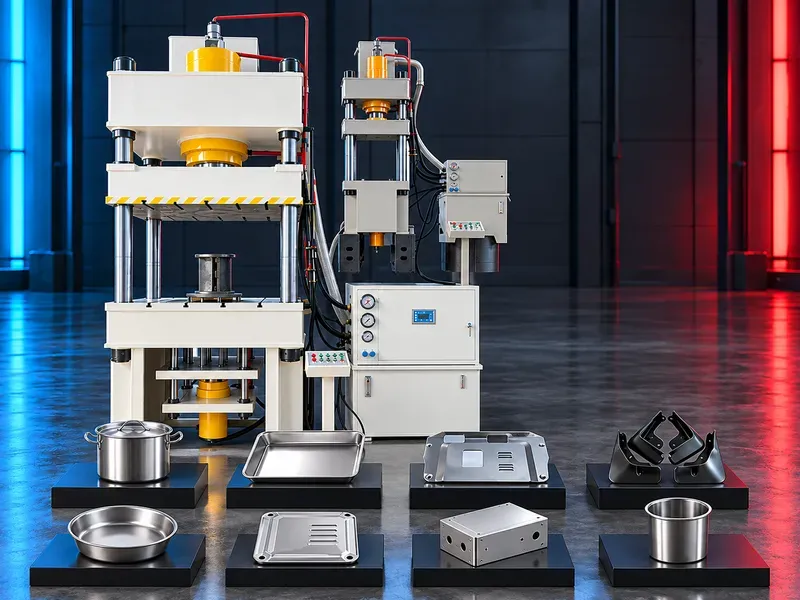
A sheet metal stretching hydraulic press forms approved sheet blanks through controlled force and tool movement. Depending on the verified configuration it may support drawing blanking punching flanging and combined forming sequences for industrial components.
The press applies hydraulic force through a die set selected for the part material thickness geometry draw depth and required finish. Stable pressure controlled motion and suitable blank holding help produce formed parts with repeatable dimensions. Hydraulic cushions or buffers may support drawing followed by punching or punching followed by flanging when these functions are included in the approved machine and tooling package. The exact sequence capacity and control method require confirmation from the official data sheet. Typical industrial uses may include approved parts for vehicles motorcycles appliances petrochemical equipment rail transport and aerospace supply chains. Suitability is determined by the component drawing process trial and acceptance criteria rather than the industry name alone.
What the press does
The press moves a forming tool under controlled hydraulic force to stretch or draw an approved sheet blank into the required shape. The process may also include blanking punching trimming or flanging when supported by the machine tooling and controls.
Part quality depends on material behavior blank preparation die design lubrication force distribution stroke control and inspection.
Sheet drawing and stretching
Drawing forms a flat blank into a three dimensional part while controlling material flow between the punch die and blank holder. Correct blank holding helps limit wrinkling tearing and excessive thinning.
Define draw depth radii wall profile flange condition and permitted thinning on the approved part drawing.
Blanking and punching
Blanking separates the required outline from sheet material while punching creates approved openings or cut features. Cutting clearance tool condition and support affect edge quality and tool life.
Confirm whether cutting occurs before during or after drawing and how scrap and finished parts are removed safely.
Flanging and combined processes
Flanging forms an edge around an opening or part perimeter for stiffness joining or assembly. A verified process may combine drawing with punching or punching with flanging to reduce handling and repeated setups.
Combined operation claims must be confirmed with the actual die design hydraulic circuit cushion functions and control sequence.
Hydraulic cushion and blank holding
A hydraulic cushion or buffer may provide controlled resistance support ejection or blank holding according to the supplied arrangement. Stable settings help manage material flow during the forming cycle.
Verify cushion force stroke speed position control number of points and compatibility with the planned tool.
Materials and blank condition
Provide the exact sheet grade thickness mechanical properties coating surface finish rolling direction blank size and edge condition. Formability can vary between grades and production batches.
Material compatibility and thickness range require an approved data sheet and representative forming trials.
Dies and tooling
The punch die blank holder guides stops and ejectors must be engineered for the component process stages material and press interface. Tool alignment and controlled clearances are essential for repeatable forming.
Confirm tool dimensions weight mounting height shut height handling method sensors lubrication and ownership of design validation maintenance and spare components.
Hydraulic and control system
The hydraulic system generates and regulates forming force while the control system manages motion pressure dwell and cycle logic according to the supplied functions.
Verify force control position control pressure stages speed stages recipe storage diagnostics access levels data backup and safe recovery after interruption.
Part quality and process acceptance
Acceptance should define dimensions shape thickness distribution surface condition wrinkles cracks splits burrs springback and assembly fit. Cosmetic zones and critical features should be identified on the drawing.
Approve the process through representative material tool trials and measured sample parts before production release.
Typical applications
Possible applications include drawn housings covers panels containers brackets and other approved formed sheet components for automotive motorcycle appliance petrochemical rail transport and aerospace supply chains.
Every part needs a separate forming assessment because geometry material finish volume and quality requirements can change the correct machine and tooling solution.
Safety and operator protection
Press operation involves high forces moving slides dies stored hydraulic energy sharp sheet edges and automatic auxiliaries. Guards interlocked access emergency stops safe control functions and tooling protection should follow the approved risk assessment.
Safe procedures must cover tool setup loading trial cycles production unloading jam recovery cleaning inspection and maintenance.
Automation and material handling
Depending on the approved configuration blanks may be loaded manually or by feeders robots transfer devices or lifting equipment. Finished part and scrap removal must be coordinated with the press cycle.
Confirm production volume part mass ergonomics safety interfaces and the required level of automation before selection.
Installation and site readiness
Site planning should confirm foundation and floor loading machine height access route electrical supply hydraulic oil cooling compressed air drainage ventilation lighting and maintenance clearance.
Tool change space lifting capacity material flow and protected storage for dies and blanks should be included in the layout.
Training maintenance and lifecycle support
Training should cover safe operation recipes tool setup drawing sequence quality checks hydraulic settings alarm recovery lubrication and daily inspection.
Preventive maintenance should address oil quality filtration seals cylinders pumps valves guides sensors guards safety devices cooling and electrical controls. Prepare approved spare parts and consumables.
How to select the correct press
Start with the part drawing material certificate thickness blank size draw depth forming stages quantities quality criteria die concept and automation target. Include the largest tool weight and required working envelope.
Selection should be based on a forming study and verified trials that confirm required force energy stroke bed area cushion behavior process speed and part quality.
Technical information requiring verification
Verify nominal force system pressure slide stroke daylight bed and slide dimensions approach pressing and return speeds cushion force and stroke ejector functions accuracy cycle time motor power cooling oil capacity electrical load dimensions foundation load and machine weight.
Confirm control functions guarding standards tooling interface automation connections installation commissioning training warranty service scope spare parts and acceptance tests from approved documentation.
Publishing status
This page describes the machine category applications and selection logic. Exact capacities speeds accuracy productivity compatible materials functions options standards and commercial commitments require an approved model data sheet and technical review before publication.
Questions we are asked
What is a sheet metal stretching hydraulic press?
It is a hydraulic forming machine that draws or stretches an approved sheet blank into a shaped part through controlled force tool motion and blank holding.
Which operations can it perform?
Possible operations include drawing stretching blanking punching trimming and flanging when these functions are supported by the approved machine tooling and control package.
What causes wrinkles or tearing during drawing?
Material properties blank shape die radii lubrication blank holding force draw depth alignment and process settings can all affect wrinkling tearing and thinning.
Can drawing and punching be completed in one cycle?
A combined sequence may be possible when the hydraulic cushion die design controls and safety arrangement are engineered for it. The exact process requires technical verification.
How is the correct press selected?
Selection starts with the part drawing material thickness blank size forming stages quantities quality criteria die data and automation target followed by a verified forming study and trial.
What information is required for a technical proposal?
Provide the part drawing material certificate annual quantity required operations existing tool data quality criteria utilities site layout and preferred loading method.
Tell us the part you need to make
An engineer reads every request. Usually the same working day.
Related
- CNC Hydraulic Press Brake CNC-controlled hydraulic press brakes for bending sheet metal components according to defined angles, dimensions and production requirements.
- CNC TUBE BENDING MACHINE CNC tube bending machines control the bending sequence to produce defined tube and pipe geometries. Selection depends on the material, section, diameter, wall thickness, bend radius, part geometry, accuracy, and production volume.
- CNC Gantry Plasma Cutting Machines A CNC gantry plasma cutting machine moves one or more cutting stations across a guided bridge to process suitable electrically conductive plate and supported profiles. The correct configuration depends on the material, thickness, plate size, part geometry, edge quality, bevels, secondary operations, extraction, automation, and required output.