

METAL PROFILE FORMING MACHINES
Section Profile Bending Machines
Section profile bending machines form compatible metal profiles into controlled curves and rings using driven and adjustable rolls. Correct selection depends on the profile shape and orientation, material condition, section dimensions, required radius, finished geometry, batch size, handling method, and production target.
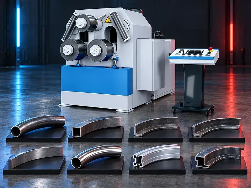
The machine feeds a straight profile between shaped rolls that apply progressive bending force. Roll position, tooling geometry, drive arrangement, pass sequence, material behavior, and operator setup influence the resulting radius, straight ends, twist, section distortion, and surface condition. Potential work may include angles, channels, flats, bars, pipes, tubes, and selected custom sections, but every shape requires an approved capacity table and suitable rolls. Machine orientation, roll configuration, hydraulic force, torque, speed, controls, supports, and automation vary and must be confirmed for the exact machine.
How profile bending works
Driven rolls move the profile through the forming zone while one or more adjustable rolls change position to create curvature. The required shape is normally reached through controlled movement and one or more passes according to the material and section.
Roll spacing, shaft arrangement, force, torque, speed, friction, tooling contact, profile orientation, springback, and pass sequence influence the final result. The approved operating method must match the selected machine and section.
Profile shapes and orientation
Potential profiles include equal and unequal angles, channels, flat bars, solid bars, round pipe, square tube, rectangular tube, tees, beams, and selected extruded or fabricated sections when supported by verified capacity data.
The same profile can have different capacities when bent in another orientation. Leg position, web direction, seam location, open side direction, wall thickness, corner radius, and section symmetry must be stated before selection.
Roll configuration and machine orientation
Profile bending machines can use different roll layouts, shaft positions, drive arrangements, and adjustment methods. Some configurations may operate horizontally, vertically, or in more than one working orientation according to the approved design.
The number of driven rolls, shaft diameter, center distances, guide arrangement, roll movement, support system, and working orientation affect access, capacity, handling, and the range of profiles. These details require exact model confirmation.
Forming rolls and tooling
Rolls should support the profile at suitable contact areas while providing clearance for the section shape. Standard rolls may cover common profiles, while dedicated tooling may be required for tubes, thin walls, decorative sections, or parts with sensitive surfaces.
Roll material, hardness, diameter, width, groove geometry, spacers, bearings, shaft fit, retention, surface finish, and change procedure must be verified. Tooling approval should include the exact profile drawing and bending orientation.
Capacity tables and machine selection
A profile bending machine cannot be selected from nominal section width alone. Capacity depends on section shape, dimensions, wall or web thickness, material grade, yield strength, orientation, required radius, arc length, straight ends, pass count, and tooling.
Approved capacity tables should identify the profile, orientation, material basis, section dimensions, minimum stated radius, and any special tooling or operating conditions. Values from another machine or a similar profile should not be reused.
Bending radius and finished geometry
The required result may be an arc, ring, spiral, variable radius part, or another supported curve. The drawing should define the reference radius, inside or outside dimension, arc length, included angle, chord, rise, straight ends, closure, and joining allowance where relevant.
Minimum radius, achievable tolerance, roundness, closure, and straight end length depend on the exact profile, material, rolls, machine geometry, setup, and inspection method. They require documented confirmation or an approved trial.
Material behavior and springback
After leaving the rolls, the material can recover elastically and open the formed radius. Springback varies with material grade, temper, yield strength, section stiffness, rolling direction, heat treatment, weld seam, previous forming, and required radius.
Compensation should be established through approved process data or trials. Carbon steel, stainless steel, aluminum, copper alloys, and other materials should only be listed when the capacity and forming method have been verified for their exact condition.
Section distortion and twist control
Profile bending can cause flange movement, web buckling, tube ovality, wall collapse, local marking, twist, camber, or loss of symmetry. Risk increases with thin walls, open sections, tight radii, unsupported legs, poor tooling fit, and unsuitable pass planning.
Lateral guides, side supports, correction rolls, mandrels, fillers, dedicated tooling, staged passes, and orientation changes may help when approved for the application. The required controls depend on the profile and should be validated on a sample.
Hydraulic force and roll drive
Depending on the design, hydraulic systems may position forming rolls, operate supports, or apply controlled forming force. Roll rotation may be hydraulic, mechanical, or electromechanical, with one or more rolls driven according to the machine configuration.
Forming force, roll torque, motor power, hydraulic pressure, drive speed, synchronization, overload protection, slip behavior, and low speed control must be confirmed from approved documents for the exact machine.
Manual digital and programmed control
Control can range from manual adjustment with position indicators to digital readouts, repeatable position control, stored programs, and selected automatic sequences. The available functions depend on the machine configuration.
Controller type, controlled axes, position resolution, compensation, program capacity, language, data storage, backup, user access, diagnostics, remote support, and optional functions require verification. Programmed movement does not remove the need for measurement and first part approval.
Prebending and straight ends
Profile ends may remain partly straight because the complete section cannot always enter the effective forming zone. The remaining straight length depends on roll geometry, tooling, profile stiffness, machine layout, and the approved operating method.
Prebending, reversing the part, extra stock, end trimming, local correction, or dedicated tooling may reduce straight ends in some applications. The achievable result and added process steps should be agreed from the drawing and trial.
Pass planning and repeatability
A forming plan should define profile orientation, roll set, starting position, pass sequence, position changes, feed direction, speed, support settings, reversal points, measurement stages, and final correction.
Repeatability depends on stable material properties, consistent profile dimensions, controlled tooling, machine condition, calibrated position feedback, loading method, operator practice, and inspection. It should not be guaranteed from the machine category alone.
Material handling and supports
Long, heavy, flexible, or closed ring parts may need roller stands, side supports, lifting equipment, guided tables, cranes, or dedicated fixtures. Handling should prevent uncontrolled movement, sagging, rotation, scratching, collision, and excessive load on the machine shafts.
The layout should allow safe feeding, part rotation, discharge, inspection, and transfer to the next process. Support load, height range, travel, floor area, lifting points, operator positions, and exclusion zones require planning.
Production workflow
The process normally starts by reviewing the drawing, confirming the material and profile, checking tooling and machine condition, setting the profile orientation, installing and aligning rolls, preparing supports, and establishing the forming sequence.
The operator then performs controlled passes, measures the developing shape, applies approved corrections, checks the final geometry, marks the part for traceability, and releases it according to the inspection plan.
Quality inspection
Inspection may cover radius, diameter, chord, rise, angle, arc length, straight ends, roundness, closure, twist, flatness, section dimensions, ovality, wall condition, surface marks, and joint fit according to the drawing.
Templates, tapes, calipers, height gauges, angle tools, profile gauges, fixtures, laser measurement, optical systems, or coordinate measurement may be used when suitable. The method, datum, tolerance, sampling, and calibration status should be defined before production.
Industrial applications
Potential applications include structural arches, frames, rings, handrails, architectural metalwork, tanks and vessels, transport components, machinery frames, agricultural equipment, energy projects, pipe systems, and general fabricated products.
Application suitability depends on the drawing, profile standard, material traceability, structural requirements, forming allowance, welding sequence, heat treatment, surface finish, inspection, and applicable fabrication code.
How to choose the correct machine
Provide profile drawings and standards, material grades and strength, section dimensions, wall and web thickness, bending orientation, minimum and maximum radius, arc or ring geometry, straight end limits, tolerances, surface requirements, part length and mass, quantities, and target output.
Also define tooling needs, loading and support method, horizontal or vertical working preference, available floor space, utilities, operator access, inspection method, future profile range, safety rules, and the next forming or joining operation.
Technical information to verify
Approved documents must confirm the machine structure, roll arrangement, driven rolls, shaft dimensions, roll diameters, center distances, profile capacities by orientation, minimum stated radii, forming force, torque, speed, motor power, hydraulic system, controls, supports, dimensions, weight, and foundation.
The included roll set, optional rolls, side guides, correction devices, position indicators, programmed axes, working orientation, lubrication, electrical supply, hydraulic oil, guarding, noise basis, documentation, training, and acceptance method also require written confirmation.
Safety and operating risks
Risks include trapping between rolls and profile, entanglement, rotating work, unexpected part movement, springback, falling or swinging sections, sharp edges, hydraulic pressure, tool change, heavy handling, electrical hazards, and stored energy.
Controls should include approved guards, emergency stops, safe control devices, exclusion zones, supported material, lifting plans, secure tooling, suitable personal protective equipment, training, supervision, maintenance isolation, and a documented site risk assessment.
Installation and commissioning
Site preparation should confirm delivery access, unloading, floor capacity, foundation, anchoring, leveling, electrical isolation, hydraulic service, lighting, working clearances, guards, material routes, lifting equipment, support locations, and maintenance access.
Commissioning should include geometry and alignment checks, roll and shaft inspection, lubrication, hydraulic and electrical tests, position calibration, control and safety validation, tooling setup, trial bending, sample inspection, operator training, maintenance training, and document handover.
Maintenance and lifecycle support
Preventive maintenance should follow approved schedules for rolls, shafts, bearings, guides, gearboxes, drive components, hydraulic oil, filters, hoses, seals, lubrication, sensors, controls, guards, emergency systems, fasteners, alignment, and wear inspection.
Recommended spare bearings, seals, hoses, filters, lubricants, drive parts, sensors, tooling components, calibration devices, backups, service tools, technical support, training, and documents should be agreed for the selected machine.
Limitations and publishing status
The supplied description does not prove a capacity for every angle, channel, pipe, tube, custom section, material, or radius. It also does not verify bending accuracy, rigidity, repeatability, easy operation, production rate, surface quality, standard tooling, or distortion limits.
The page needs an approved datasheet for the exact machine, verified capacity tables, confirmed roll and control configuration, approved images, technical review, staging review, and final content approval before publication.
Technical review and next step
Send the profile drawing, material specification, section dimensions, bending orientation, required radius, finished geometry, tolerances, surface requirements, quantities, part length and mass, and available handling method for technical review.
The review should compare the application with approved capacity tables and identify the suitable machine configuration, roll set, supports, pass plan, inspection method, site requirements, and any sample trial needed before selection.
Questions we are asked
What is a section profile bending machine?
It is a forming machine that passes a compatible metal profile through shaped rolls to produce a controlled arc ring or other supported curve.
Which profiles can the machine bend?
Possible sections include angles channels flats bars pipes tubes and selected custom profiles only when the exact shape orientation dimensions material and radius are covered by approved capacity data.
How is the correct machine size selected?
Selection requires the profile drawing material strength section dimensions bending orientation required radius finished geometry tolerances part mass quantities tooling supports and site conditions.
Can one roll set bend every profile?
No. Roll geometry must support the exact section. Some profiles need spacers side guides dedicated rolls or other approved tooling to limit distortion and marking.
Is the final radius guaranteed from the machine setting?
No. Material variation springback tooling machine condition pass planning handling and measurement affect the result. The process may require a verified trial and first part approval.
Tell us the part you need to make
An engineer reads every request. Usually the same working day.
Related
- CNC Hydraulic Press Brake CNC-controlled hydraulic press brakes for bending sheet metal components according to defined angles, dimensions and production requirements.
- CNC TUBE BENDING MACHINE CNC tube bending machines control the bending sequence to produce defined tube and pipe geometries. Selection depends on the material, section, diameter, wall thickness, bend radius, part geometry, accuracy, and production volume.
- CNC Gantry Plasma Cutting Machines A CNC gantry plasma cutting machine moves one or more cutting stations across a guided bridge to process suitable electrically conductive plate and supported profiles. The correct configuration depends on the material, thickness, plate size, part geometry, edge quality, bevels, secondary operations, extraction, automation, and required output.