

SHEET METAL EDGE FORMING MACHINES
Motorized Bordering and Trimming Machines
A motorized bordering and trimming machine supports controlled edge finishing on compatible sheet metal parts. The correct machine and tooling depend on the part geometry, material, thickness, edge profile, dimensional tolerance, surface requirement, and production target.
Bordering and trimming are finishing operations used to prepare an edge to the required contour, height, or profile. Depending on the verified configuration, the workpiece is supported and rotated while a cutting tool or forming rolls act on the edge. The machine should be selected from an approved part drawing and process plan. Workpiece diameter, depth, material grade, thickness, seam position, edge allowance, required finish, guarding, loading method, and expected batch pattern must be reviewed before confirming suitability.
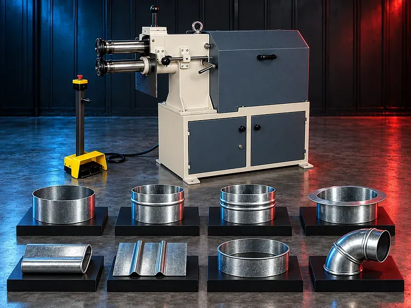
What the machine does
The machine is intended to perform controlled trimming and edge forming on suitable sheet metal workpieces. Trimming removes excess edge material to establish the required height or contour, while bordering forms or finishes the edge through compatible tooling.
The exact operations available depend on the machine structure, drive system, work support, forming rolls, cutting unit, adjustment method, and approved tooling package. The operation sequence must be confirmed for the selected configuration.
Typical process sequence
The workpiece is first inspected against the drawing and checked for deformation, weld condition, surface damage, and sufficient edge allowance. It is then located and clamped using the approved support and holding method.
The operator sets the tooling position, rotation direction, speed where adjustable, and feed or forming pressure according to the approved process. A sample part should be inspected before batch production begins.
After trimming or forming, the edge is checked for height, profile, roundness, burrs, cracks, surface marks, and dimensional consistency. Deburring or an additional finishing operation may be required.
Trimming operation
Trimming can establish a consistent edge after pressing, spinning, rolling, welding, or another upstream forming process. Tool geometry, support rigidity, cutting clearance, workpiece rotation, feed, and material behavior affect the result.
The machine must not be assumed to produce a finished edge without secondary work. Burr condition, edge quality, distortion, and the need for deburring or calibration should be verified through approved trials.
Bordering and edge forming
Bordering uses matched or purpose designed tools to shape the edge into the required profile. The operation may include curling, beading, flanging, stiffening, or another supported edge form when the machine and tooling are designed for that task.
Profile radius, edge angle, flange width, bead shape, material springback, seam location, and surface sensitivity should be defined on the approved drawing. Tooling suitability must be confirmed before production.
Workpiece support and rotation
Stable support and controlled rotation are important for a consistent edge. The holding system should locate the workpiece without unacceptable deformation, slipping, marking, or interference with the cutting and forming zones.
Workpiece mass, diameter, depth, center of gravity, stiffness, and loading orientation determine the required support and handling arrangement. Large or unstable parts may require additional handling equipment.
Motorized drive and controls
The motorized drive provides rotation or powered movement according to the machine design. Controls may coordinate start, stop, direction, speed, tool approach, and emergency functions when these features are included in the verified configuration.
Motor power, speed range, torque, transmission, electrical supply, control type, overload protection, braking, and cycle functions require confirmation from the approved technical documentation.
Tooling and changeover
Cutting tools, forming rolls, supports, clamps, and guides should match the workpiece geometry and material. Tooling condition directly affects edge profile, surface quality, dimensional consistency, vibration, and operating safety.
Changeover time depends on the tooling design, adjustment method, work support, part variety, and inspection procedure. Required tool sets, spare tools, setup gauges, and storage arrangements should be defined before purchase.
Materials and forming behavior
Material suitability cannot be confirmed from the machine category alone. Grade, temper, hardness, coating, surface finish, thickness, weld condition, ductility, and springback influence cutting and forming performance.
Carbon steel, stainless steel, aluminum, copper, coated sheet, or other materials should only be listed after the supplier confirms the exact machine and tooling against approved samples or material data.
Applications
Potential applications include compatible circular or formed sheet metal components used in ventilation, containers, light fabrication, metal furniture, kitchen equipment, tanks, enclosures, and general industrial products.
Application suitability depends on the actual part geometry and required operation. A sample drawing or part should be reviewed because the machine may not support every diameter, depth, profile, seam, material, or finish.
Quality and inspection
Inspection should cover the dimensions that matter to the next assembly or process. These may include edge height, diameter, roundness, flange width, profile radius, burr condition, flatness, surface marks, cracks, and consistency around the circumference.
The inspection method, measuring tools, sampling frequency, acceptance limits, reference drawing, first part approval, and nonconforming part procedure should be established in the process plan.
How to choose the correct machine
Provide the finished part drawing and the condition of the part before trimming or forming. Include material grade, thickness, minimum and maximum diameters, depth, edge allowance, required profile, tolerance, surface requirement, seam details, and annual quantities.
Also define batch size, part change frequency, available electrical supply, floor space, loading method, operator access, safety requirements, upstream process, downstream process, and required inspection method.
Technical information to verify
Approved documents must confirm the supported operations, workpiece range, thickness range, material limits, tool travel, spindle or work rotation range, feed or pressure adjustment, motor power, electrical supply, controls, tooling, dimensions, weight, and installation requirements.
Claims about speed, accuracy, output, one person operation, automatic cycles, quick changeover, low maintenance, or finished edge quality require evidence from the exact configuration and should not be published before technical approval.
Safety and operating risks
Risks include rotating workpieces, cutting edges, sharp swarf, pinch and crush zones, moving rolls, tool breakage, ejected parts, entanglement, electrical hazards, and unsafe manual handling.
The final installation should include the approved guards, emergency stops, interlocks where specified, safe controls, work support, operating procedures, personal protective equipment, training, and local risk assessment.
Installation and lifecycle support
Site planning should confirm floor condition, access route, unloading, positioning, leveling, electrical isolation, work area, lighting, material flow, handling equipment, and safe maintenance access.
Commissioning should cover installation checks, tooling setup, trial parts, operating limits, inspection method, operator training, and maintenance handover. Preventive maintenance should follow approved instructions for the drive, transmission, bearings, guides, clamps, cutting tools, forming rolls, guards, and electrical controls.
Recommended spare parts, wear tools, lubricants where applicable, inspection gauges, service intervals, technical documents, and support scope should be agreed for the selected machine.
Limitations and publication status
This is generic category content based only on the supplied machine name. It does not confirm model capacity, compatible materials, part sizes, tooling, accuracy, output, electrical data, automation, warranty, availability, or commercial terms.
The page requires an approved datasheet or manual for the exact machine, technical review, approved images, staging review, and final content approval before publication.
Questions we are asked
What is a motorized bordering and trimming machine?
It is a sheet metal finishing machine that rotates or drives a supported workpiece while compatible cutting or forming tools trim and shape its edge.
Can one machine perform both trimming and edge forming?
Some configurations may support both operations with the correct units and tooling. The exact sequence and included functions require confirmation from the approved technical document.
Which materials can it process?
Material suitability must be verified for the exact machine and tooling. Provide the material grade thickness temper coating surface requirement and a part drawing.
Can it process every circular sheet metal part?
No. Suitability depends on diameter depth geometry seam location stiffness edge allowance support tooling tolerance and safe loading.
What information is needed for selection?
Provide the part drawing material thickness diameter range depth edge profile tolerance surface requirement batch size annual quantity upstream condition electrical supply floor plan and handling method.
Tell us the part you need to make
An engineer reads every request. Usually the same working day.
Related
- CNC Hydraulic Press Brake CNC-controlled hydraulic press brakes for bending sheet metal components according to defined angles, dimensions and production requirements.
- CNC TUBE BENDING MACHINE CNC tube bending machines control the bending sequence to produce defined tube and pipe geometries. Selection depends on the material, section, diameter, wall thickness, bend radius, part geometry, accuracy, and production volume.
- CNC Gantry Plasma Cutting Machines A CNC gantry plasma cutting machine moves one or more cutting stations across a guided bridge to process suitable electrically conductive plate and supported profiles. The correct configuration depends on the material, thickness, plate size, part geometry, edge quality, bevels, secondary operations, extraction, automation, and required output.