

HYDRAULIC FORMING PRESSES
Four Column Hydraulic Presses
Four column hydraulic presses apply controlled pressing force through a guided moving slide for compatible forming, drawing, pressing, straightening, trimming, and assembly operations. Correct selection depends on the process, material, part geometry, required force, tooling, stroke, working space, speed, quality criteria, automation, and safety requirements
The machine uses a hydraulic system to move the press slide toward tooling mounted in the working area. Four columns connect and guide the main structures according to the machine design, while the cylinder system develops the force and motion required by the approved process. Machines in this category can differ in frame construction, cylinder arrangement, nominal force, slide and ejector force, stroke, daylight, table size, speed stages, pressure control, operating modes, guarding, and optional handling systems. Every value and application must be confirmed for the exact machine and tool
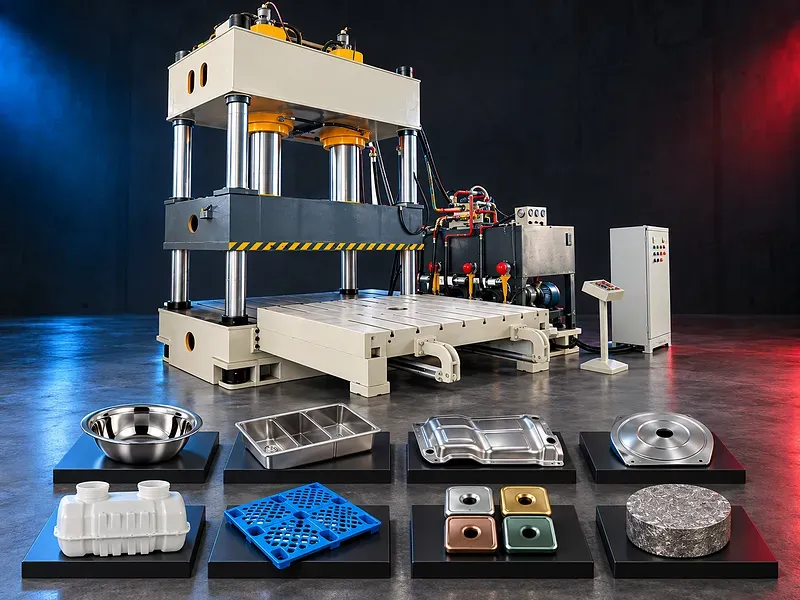
How a four column hydraulic press works
A hydraulic pump sends oil through controlled valves to one or more cylinders. Cylinder movement drives the slide through the working stroke so the mounted tool applies force to the material or component.
The return movement, pressure release, decompression, dwell, speed change, and end positions depend on the hydraulic and control design. The approved sequence should match the tool, material, process, and risk assessment.
Four column frame and slide guidance
The four columns connect or guide the upper beam, moving slide, and lower working structure according to the machine construction. Column spacing and clear opening influence tooling access, part handling, and the usable working envelope.
Column diameter, material, surface treatment, guide bushings, lubrication, parallelism, frame stiffness, tie system, and allowable off center loading require exact technical confirmation. A four column layout does not by itself guarantee accuracy or rigidity.
Pressing force and working pressure
Nominal pressing force is related to hydraulic pressure and effective cylinder area, but available force can vary through the stroke and with circuit settings. The process force should be calculated from the material, part, tool, friction, forming stage, and required margin.
Rated force, permissible working pressure, overload protection, pressure adjustment range, force indication, calibration method, pressure stability, and continuous duty conditions must be confirmed from approved documents.
Main cylinder and return system
The main cylinder or cylinder group moves the slide and generates the forming force. Return movement may use hydraulic return cylinders, the main cylinder, or another approved arrangement according to the machine design.
Cylinder bore, rod diameter, seals, guides, mounting, rated pressure, return force, speed, cushioning, venting, leakage limits, alignment, and maintenance method require verification for the exact machine.
Stroke daylight and working envelope
Slide stroke defines the permitted movement range, while daylight describes the open distance available in the press according to the stated reference condition. Tool height, material thickness, part depth, loading clearance, ejector movement, and safety distance must fit within the verified envelope.
Maximum stroke and daylight are not interchangeable. Minimum shut height, slide position limits, table thickness, bolster, adapters, tool change space, and any adjustable stop should be included in the application review.
Working table and moving slide
The lower table and moving slide support and locate the die set. Their dimensions, slot pattern, mounting holes, flatness, parallelism, allowable load, local load limits, and surface condition affect tool installation and process stability.
Tool reactions should remain within the approved loading zone. Concentrated or offset loads, large dies, deep parts, and asymmetric forming can require reinforced structures, additional guidance, or a different press design.
Speed stages and cycle control
A hydraulic press may provide approach, pressing, decompression, return, and slow setup speeds according to its circuit and controls. Faster approach can reduce nonworking time while the forming stage may require a controlled lower speed.
Approach speed, working speed, return speed, transition point, acceleration, deceleration, dwell, cycle time, thermal limits, pump flow, and duty pattern must be verified. Production rate should not be calculated from one speed value alone.
Pressure holding and dwell
Some forming or bonding processes may require the press to hold a position or pressure for a defined time. The control method can use pressure switches, transducers, valves, timers, or programmed logic according to the approved machine configuration.
Holding tolerance, pressure decay, oil temperature, internal leakage, tool deflection, material relaxation, dwell range, and release sequence affect the result. The required process window should be validated through an approved trial.
Operating modes and control system
Potential modes include setup, inching, manual, semiautomatic, and automatic cycles when supported. The operator may set pressure, position, stroke limits, speed transition, dwell, ejector sequence, and cycle logic according to the installed control system.
Controller type, display, controlled axes, sensors, position resolution, program storage, language, alarms, permissions, data backup, diagnostics, connectivity, and optional functions require written confirmation.
Tooling and die installation
The die set converts press force and movement into the required operation. Tool design should consider process force, shut height, guidance, material flow, blank holding, clearances, venting, ejection, wear, lubrication, alignment, and safe handling.
Tool mass, center of load, mounting method, slots, clamps, adapters, lifting points, storage, tool change method, trial procedure, maintenance, and ownership should be agreed before machine selection.
Ejector cushion and auxiliary functions
A lower ejector, hydraulic cushion, blank holder, knock out device, heating or cooling circuit, moving bolster, light curtain, feeder, or transfer system may be available on selected configurations. These functions are not standard across the category.
Force, stroke, speed, position, timing, mounting, control integration, utility needs, tool interface, safety logic, and included scope must be confirmed separately for every auxiliary function.
Drawing and forming operations
Potential processes include shallow or deep drawing, forming, flanging, embossing, calibration, pressing, straightening, trimming, punching, blanking, assembly, and selected compaction tasks when the machine and tooling are designed and approved for them.
Process suitability depends on material grade and condition, blank dimensions, draw ratio, geometry, lubrication, blank holding, die clearance, force curve, stroke, speed, temperature, quality criteria, and safety requirements.
Material handling and automation
Large blanks, heavy dies, deep parts, hot components, or repetitive production may need cranes, loading tables, rolling bolsters, feeders, robots, transfers, conveyors, part supports, or dedicated fixtures.
The handling concept should control part orientation, tool access, pinch points, dropped loads, cycle interlocks, scrap removal, surface protection, inspection access, and transfer to the next process.
Process setup and production workflow
Setup should begin with the approved drawing, material specification, process sheet, force calculation, die record, shut height, lubrication plan, handling method, press settings, inspection plan, and safety validation.
The production cycle may include material identification, blank preparation, tool inspection, die installation and alignment, controlled setup strokes, first part forming, measurement, correction, approval, batch production, traceability, and final release.
Quality and process validation
Inspection may cover dimensions, depth, profile, flatness, angles, wall thinning, cracks, wrinkles, springback, surface marks, burrs, hole position, trim condition, assembly force, and visual appearance according to the part drawing.
The quality plan should define measurement equipment, datum, tolerances, sampling, calibration, first part approval, process monitoring, control limits, nonconforming part handling, and records. Machine force or pressure indication does not replace part inspection.
Industrial applications
Potential applications include compatible cookware, sinks, trays, covers, electrical enclosures, appliance panels, automotive parts, industrial containers, hardware, structural components, rubber or composite forming, assembly, and general metal products.
Every application requires review of material, geometry, tool design, production quantity, required finish, inspection, downstream operations, site conditions, and the applicable product or safety standard.
How to choose the correct press
Provide part and tool drawings, material grade and condition, blank dimensions and thickness, finished geometry, operation sequence, calculated force, force through the stroke, required working speed, stroke, daylight, table area, shut height, ejector or cushion needs, tolerances, quantities, and target output.
Also define die mass, loading method, automation, utilities, shift pattern, floor space, foundation, operator access, inspection method, safety concept, maintenance resources, future parts, and acceptance trial requirements.
Technical information to verify
Approved documents must confirm the frame construction, nominal pressing force, return force, ejector or cushion force, stroke, daylight, table and slide dimensions, column spacing and diameter, approach working and return speeds, pressure range, motor and pump data, oil capacity, controls, and accuracy conditions.
Machine dimensions, weight, floor loading, foundation, electrical supply, cooling, noise test basis, lubrication, guards, safety functions, standard equipment, optional equipment, tooling interface, environmental conditions, documentation, training, and acceptance method also require confirmation.
Safety and operating risks
Risks include crushing in the die area, slide movement, ejection, tool failure, stored hydraulic pressure, hose failure, unexpected automatic motion, falling dies, sharp blanks, hot parts, manual handling, electrical hazards, noise, and maintenance work.
The safety concept should include approved guarding, interlocked access, light curtains where suitable, emergency stops, safe control logic, setup mode protection, die blocks, pressure isolation, lockout procedures, lifting plans, inspection, training, supervision, and a documented risk assessment.
Installation and commissioning
Site preparation should cover delivery access, unloading, floor capacity, foundation, anchoring, leveling, electrical isolation, hydraulic oil, cooling if required, lighting, working clearances, guards, die handling, material flow, scrap removal, and maintenance access.
Commissioning should include geometry, level, slide and table alignment, column and guide inspection, hydraulic flushing and pressure tests, electrical and control tests, sensor calibration, safety validation, tool setup, trial production, sample inspection, training, and document handover.
Maintenance and lifecycle support
Preventive maintenance should follow approved schedules for hydraulic oil, filters, pumps, valves, cylinders, seals, hoses, coolers, columns, bushings, slide guides, lubrication, fasteners, sensors, controls, guards, interlocks, emergency systems, and alignment.
Recommended seals, hoses, filters, lubricants, valve components, sensors, guide parts, calibration devices, software backups, service tools, technical support, training, inspection records, and documents should be agreed for the selected press.
Limitations and publishing status
The supplied image identifies the general four column hydraulic press category but does not verify force, stroke, daylight, table size, speeds, control functions, accuracy, available tooling, production output, safety scope, or suitability for any shown product.
The page needs an approved datasheet for the exact machine, verified application and capacity data, confirmed included equipment, approved media rights, technical review, staging review, and final content approval before publication.
Technical review and next step
Send part drawings, material details, blank dimensions, operation sequence, tool drawings, calculated force, required stroke and working space, tolerances, quantities, target output, handling method, available utilities, and site layout for technical review.
The review should compare the process with approved machine data and identify the suitable press configuration, tool interface, auxiliary systems, safety concept, acceptance trial, installation requirements, training, maintenance, and spare parts scope.
Questions we are asked
What is a four column hydraulic press?
It is a hydraulic press with a moving slide guided within a four column structure to apply controlled force to compatible tooling and workpieces.
Which operations can the press perform?
Possible operations include forming drawing pressing straightening trimming punching assembly and selected compaction tasks only when the exact press tooling material and safety system are approved for the process.
How is the required press force selected?
Force should be calculated from the material part geometry operation tool friction forming stage and safety margin then checked against the approved force conditions through the machine stroke.
Does nominal force define the complete press capacity?
No. Selection also depends on stroke daylight table area shut height speed off center loading tooling auxiliary functions duty pattern and safety requirements.
What information is needed for technical selection?
Provide part and tool drawings material details blank dimensions process sequence calculated force stroke working space tolerances quantities target output handling method utilities and site layout.
Tell us the part you need to make
An engineer reads every request. Usually the same working day.
Related
- CNC Hydraulic Press Brake CNC-controlled hydraulic press brakes for bending sheet metal components according to defined angles, dimensions and production requirements.
- CNC TUBE BENDING MACHINE CNC tube bending machines control the bending sequence to produce defined tube and pipe geometries. Selection depends on the material, section, diameter, wall thickness, bend radius, part geometry, accuracy, and production volume.
- CNC Gantry Plasma Cutting Machines A CNC gantry plasma cutting machine moves one or more cutting stations across a guided bridge to process suitable electrically conductive plate and supported profiles. The correct configuration depends on the material, thickness, plate size, part geometry, edge quality, bevels, secondary operations, extraction, automation, and required output.