

TANK HEAD FORMING MACHINES
Dished Head Flanging Machines
A dished head flanging machine forms the knuckle and straight flange of supported vessel heads after the blank has been prepared or dished. The correct configuration depends on the head diameter, thickness, material, profile, central opening, forming temperature, tooling, handling, tolerance, and required output.
Dished head production commonly separates the dishing operation from the flanging operation. During flanging, the formed blank is supported and rotated while a knuckle roll and opposing support apply controlled pressure and position to create the required transition radius and flange. The supplied description refers to proportional hydraulics, CNC controlled roll gap, automatic cycles, torque monitoring, shaft tilt, linear guides, powered carriages, hot flanging, cone forming, heads with or without central holes, loading systems, beveling, and special rolls. These are configuration dependent functions that require approved technical confirmation.
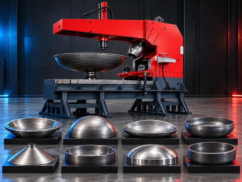
Dished head flanging principle
The machine forms the edge region of a dished blank by controlled rotation and pressure between purpose designed rolls. The process develops the knuckle radius and straight flange while supporting the head geometry.
Roll position, gap, force, rotation, support, lubrication, temperature, blank preparation, material behavior, and springback should be coordinated through an approved process plan.
Dishing and flanging workflow
A flat circular blank may first be formed into a dish by pressing, spinning, or another approved forming method. The dished blank then moves to the flanging machine to create the knuckle and flange dimensions.
Blank cutting, welding where applicable, dishing, intermediate inspection, flanging, trimming, beveling, heat treatment, surface cleaning, dimensional inspection, and certification should be planned as one production route.
Head geometries and profiles
Potential work includes supported torispherical, ellipsoidal, hemispherical, shallow, deep, flat flanged, conical, and special head geometries when the machine, rolls, support, and process are suitable.
Crown radius, knuckle radius, straight flange, depth, diameter, cone angle, central opening, ovality, tolerance, and code requirements must be defined on an approved drawing.
Knuckle roll and support rolls
The knuckle roll applies the local forming action while support and drive rolls rotate and stabilize the head. Roll profile, diameter, surface, hardness, mounting, and position should match the head geometry and material.
Additional or special rolls may be required for different radii, diameters, thicknesses, stainless steels, high alloy materials, hot work, cones, small flanges, or surface protection requirements.
Hydraulic pressure and proportional control
A hydraulic system may control roll force, carriage movement, clamping, shaft movement, and other machine functions. Proportional control can regulate pressure and position according to the verified cycle.
Claims for reduced thinning, smooth forming, or precise repeatability require validation. Maximum force, working pressure, cylinder data, valve control, compensation, oil specification, filtration, cooling, and protection settings need approved documentation.
CNC controlled roll gap
A CNC controlled gap system may coordinate the distance between forming elements during the cycle using position feedback, pressure data, programmed steps, and material response.
Sensor type, resolution, reference method, calibration, gap range, compensation logic, position and pressure limits, alarms, manual override, data storage, and achieved result require technical verification.
Automatic flanging cycle
An automatic cycle may coordinate loading position, head support, roll approach, pressure, rotation, gap changes, springback compensation, completion, and return according to the selected program.
One person operation should not be assumed. Staffing depends on head size and weight, loading equipment, temperature, inspection, guarding, automation, local rules, and the approved risk assessment.
Roll rotation and torque monitoring
Electric or hydraulic roll drives may rotate the head through the forming cycle. Torque monitoring can help identify overload, slip, binding, unexpected material response, or setup problems when correctly configured.
Drive type, speed range, torque, motor power, inverter settings, overload limits, alarm response, braking, synchronization, and safe recovery require approved technical data.
Shaft tilt and springback compensation
A tilting knuckle roll shaft or adjustable forming axis may help compensate for springback, control the flange angle, and address certain head or cone geometries according to the machine design.
Tilt range, load, locking, reference, position feedback, programmed relationship, tool clearance, material behavior, and resulting geometry must be verified through setup and sample approval.
Carriages guides and positioning
The forming assemblies may travel on linear guides or another verified guide system and may be positioned by screws, cylinders, racks, or other drive mechanisms.
Guide design does not eliminate wear or guarantee constant accuracy. Lubrication, contamination, load, alignment, screw condition, backlash, feedback, calibration, maintenance, and operating duty affect long term performance.
Cold and hot flanging
Cold flanging forms the head without intentional bulk heating when the material, thickness, geometry, equipment, and forming limits support the process. Hot flanging uses controlled heating to change forming behavior for selected heavy or difficult applications.
Hot work requires verified heating equipment, temperature measurement, uniformity, scale control, material traceability, handling, fire protection, operator protection, process limits, and heat treatment review.
Conical and tilted axis components
Conical heads or shells may require a dedicated support, tilted axis, adjustable upper beam, specialized rolls, controlled alignment, and process software according to the geometry.
Cone angle, small and large diameters, height, thickness, seam location, center opening, eccentricity, straight flange, handling, and acceptance criteria need application specific engineering.
Heads with and without central openings
A head with a central opening may use a dedicated gripping or support device, while a closed head needs another support and loading arrangement. Small openings and large center holes create different stiffness and access conditions.
Opening diameter, reinforcement, edge condition, blank history, fixture contact, deformation risk, roll clearance, loading method, and inspection should be reviewed before selecting the configuration.
Small flange and special forming devices
Small straight flanges, tight knuckle radii, unusual profiles, segmented blanks, welded heads, or sensitive surfaces may need special devices, additional rolls, protective tooling, or modified process steps.
The tooling concept should be confirmed using the finished drawing, material properties, forming history, thickness, geometry, required surface, and sample results.
Loading unloading and roll change
Large heads can require cranes, manipulators, powered supports, loading arms, turning devices, or automated systems to place, support, rotate, and remove the component safely.
Dedicated equipment may also be required to mount and remove heavy knuckle rolls. Head weight, center of gravity, temperature, lifting points, floor route, operator access, and storage should be included in the handling plan.
Beveling trimming and downstream work
A separate or integrated arm may support selected edge beveling when the tool, power, control, chip management, head support, and process are verified. Other heads may require trimming or machining on separate equipment.
Final edge preparation should match welding procedure, joint design, code, thickness, root face, angle, surface condition, inspection, and downstream assembly.
Materials and forming behavior
Potential materials may include suitable carbon steels, stainless steels, low alloy steels, aluminum alloys, and other formable materials after reviewing grade, thickness, strength, ductility, heat treatment, grain direction, welds, coatings, and forming history.
High strength, work hardening, exotic alloys, clad plate, welded blanks, thick plate, or restricted forming limits may require special rolls, hot forming, intermediate heat treatment, trials, or another process.
Thickness control thinning and springback
Forming changes local strain and can reduce thickness in some zones. The process plan should define starting thickness, minimum allowed thickness, measurement locations, forming passes, force, gap, temperature, and acceptance limits.
Minimal thinning should not be promised without evidence. Material properties, blank shape, dish geometry, knuckle radius, tooling, lubrication, temperature, force, passes, and springback all affect the result.
Quality control and inspection
Acceptance may cover outside diameter, depth, crown radius, knuckle radius, straight flange length, flange angle, circularity, ovality, profile, thickness, surface condition, weld condition, bevel, and dimensional relationship to reference points.
Inspection may use templates, profile gauges, tapes, calipers, ultrasonic thickness measurement, laser scanning, total station or coordinate methods, surface inspection, weld inspection, material identification, and code documentation as required.
Application sectors
Potential sectors include pressure vessels, tank head manufacturing, road and railway tankers, silos, storage tanks, process equipment, boilers, reactors, heat exchangers, and other fabricated vessels that use formed heads.
The uploaded image displays pressure vessels, tank heads, road and railway tankers, silos, and storage tanks as application sectors. It does not confirm suitability for a specific code, material, size, or service.
How to choose the correct machine
Provide approved head drawings, profile type, material grade, plate certificate, diameter range, thickness range, depth, crown and knuckle radii, straight flange, central opening, cone angle, weld details, hot or cold process, tolerances, quantities, and target output.
Selection should review forming force, head support, roll range, drive torque, gap control, CNC functions, hot package, cone devices, opening fixtures, small flange tools, special rolls, loading systems, roll handling, beveling, inspection, utilities, floor space, cranes, and future product range.
Technical information to verify
Approved technical documents must confirm supported head types, minimum and maximum diameter, thickness range by material and forming condition, head depth, flange range, knuckle and crown limits, central opening range, cone capability, forming force, roll dimensions, roll drive, speeds, torque, and head weight.
They must also confirm hydraulic pressure and power, CNC gap control, axis travels, shaft tilt, feedback, hot flanging package, tooling, loading and unloading, roll changing, beveling, electrical supply, cooling, lubrication, dimensions, weight, foundation, guarding, stated accuracy, test conditions, included equipment, and options.
Safety and operating risks
The risk assessment should cover large rotating heads, pinch and crushing zones, hydraulic pressure, stored energy, roll movement, workpiece slip or ejection, hot material, scale, heavy tooling, suspended loads, sharp edges, electrical hazards, noise, and maintenance isolation.
Required controls may include verified guards and interlocks, emergency stops, exclusion zones, safe distance, secure support, torque and pressure limits, lifting plans, rated handling equipment, heat protection, suitable personal protection, training, and documented lockout procedures.
Installation maintenance and lifecycle support
Site planning should cover foundation and floor loading, anchoring, leveling, electrical supply, hydraulic oil, cooling, lubrication, ventilation, heating equipment where applicable, cranes, handling routes, loading area, tooling storage, inspection space, maintenance clearance, and training.
Preventive maintenance should follow approved documents for rolls, shafts, bearings, gearboxes, motors, carriages, guides, screws, hydraulics, valves, seals, filters, oil, lubrication, cooling, sensors, feedback, controls, guards, alignment, backups, and calibration.
Limitations and alternative processes
Flanging machines require suitable preformed blanks, dedicated tooling, significant handling, and a controlled process. Very small heads, unusual profiles, heavy sections, difficult alloys, or low quantities may favor another forming route.
Depending on the head, alternatives may include pressing with dedicated dies, spinning, incremental forming, hot pressing, segmented fabrication, machining, or a combined dishing and flanging production line.
Technical review and next step
Send approved head drawings, material certificates, blank and formed dimensions, thicknesses, radii, flange, openings, welds, forming temperature, tolerances, codes, annual and batch quantities, current process, target output, utilities, floor plan, crane data, and handling method for technical review.
The technical review will identify the suitable forming method, force, roll set, gap control, head support, hot or cold process, cone or opening devices, loading, beveling, inspection plan, safety controls, installation needs, and any sample forming requirement.
Questions we are asked
What is a dished head flanging machine?
It is a forming machine that rotates and supports a prepared or dished blank while controlled rolls create the knuckle radius and straight flange of a vessel head.
What head shapes can it form?
Potential shapes include supported torispherical ellipsoidal hemispherical shallow deep conical and special profiles when the machine tooling and process are suitable.
Can it work with hot and cold forming?
Some configurations may support cold flanging hot flanging or both. Material thickness geometry heating equipment and process limits require technical verification.
Does every machine include cone tools loading and beveling?
No. Cone devices opening fixtures loading systems roll changing tools beveling arms and special rolls are configuration dependent options.
Can the process guarantee minimal thinning?
No. Thinning depends on material blank geometry profile tooling force gap temperature passes lubrication and springback and must be measured against approved limits.
What information is required for selection?
Provide approved head drawings material certificates diameters thicknesses radii flange openings cone angles weld details forming temperature tolerances codes quantities target output utilities floor plan crane data and handling method.
Tell us the part you need to make
An engineer reads every request. Usually the same working day.
Related
- CNC Hydraulic Press Brake CNC-controlled hydraulic press brakes for bending sheet metal components according to defined angles, dimensions and production requirements.
- CNC TUBE BENDING MACHINE CNC tube bending machines control the bending sequence to produce defined tube and pipe geometries. Selection depends on the material, section, diameter, wall thickness, bend radius, part geometry, accuracy, and production volume.
- CNC Gantry Plasma Cutting Machines A CNC gantry plasma cutting machine moves one or more cutting stations across a guided bridge to process suitable electrically conductive plate and supported profiles. The correct configuration depends on the material, thickness, plate size, part geometry, edge quality, bevels, secondary operations, extraction, automation, and required output.