

MECHANICAL STAMPING PRESSES
C Frame Single Crank Power Presses
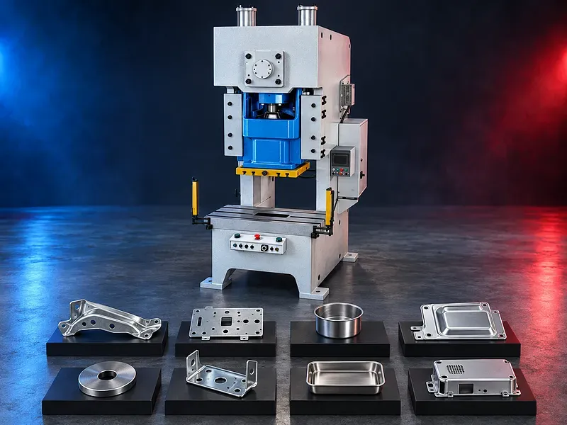
C frame single crank power presses convert rotary motion into a repeated slide stroke for compatible blanking, punching, stamping, bending, and forming operations. Correct selection depends on the process force and energy, rated point, material, tool, stroke, speed, shut height, bed area, loading condition, feeding method, duty, and safety system
EN The motor stores energy in a flywheel and the clutch connects the drive to the crankshaft when a press cycle is initiated. The crank and connecting rod move the slide through a fixed mechanical motion while the die set performs the required operation. The open front and side access of a C frame or gap frame press can support tool setup and material handling, but it also creates specific frame deflection and off center loading considerations. Tonnage, rated point, stroke, speed, die space, adjustment, controls, guards, and automation must be confirmed for the exact press.
How a single crank power press works
A motor drives a flywheel that stores rotational energy. When the clutch engages, the crankshaft turns and the connecting rod moves the slide downward and upward through the mechanical stroke.
The available force, speed, and energy change through the crank angle. Tool loading, material flow, stripping, return, and part ejection must remain within the approved press and die limits.
C frame and gap frame construction
The C shaped frame provides open access to the working area from the front and sides. This can simplify die setup, strip feeding, manual loading, part removal, and integration with compatible automation.
Frame material, welding or casting method, stress relief, machining, throat depth, deflection, angular distortion, stiffness, vibration, foundation, and permissible off center loading require exact technical confirmation.
Single crank drive system
A single crank mechanism transfers motion from the drive shaft to the slide through one main crank and connecting arrangement. The geometry defines the stroke and the relationship between slide position, speed, and force.
Crankshaft dimensions, bearings, gears, connecting rod, pins, bushings, drive ratio, balance, lubrication, heat treatment, surface finish, inspection, and permissible loads must follow approved documentation.
Flywheel motor and stored energy
The motor accelerates the flywheel and replenishes energy used during each working stroke. Flywheel energy and motor recovery must suit the process demand, speed, duty pattern, and number of operations per part.
Motor power, flywheel inertia, speed, energy curve, allowable slowdown, recovery time, starting method, electrical demand, braking, guarding, and continuous or intermittent duty require verification.
Clutch and brake system
The clutch connects the flywheel drive to the crankshaft and the brake stops and holds the slide at the intended position. Their response and control are central to safe single stroke and continuous operation.
Clutch and brake type, torque, stopping time, stopping angle, wear limits, air pressure, valve arrangement, monitoring, adjustment, test method, service interval, and replacement parts must be confirmed.
Press force rated point and capacity
Nominal tonnage is normally associated with a stated slide position or distance above the bottom of the stroke. The available force and allowable loading can be lower at other positions.
Selection requires the process force curve, rated point, energy per stroke, tool perimeter, material shear strength, forming load, stripping force, reverse load, and safety margin. A tonnage number alone is not enough.
Stroke and strokes per minute
Stroke defines the slide travel while strokes per minute describe cycle frequency under stated conditions. Fixed and adjustable stroke arrangements can have different capacity, speed, die space, and setup implications.
Stroke range, speed range, speed adjustment, single stroke rate, continuous rate, inching, thermal limits, motor recovery, feed timing, part removal, and duty restrictions require verification.
Slide guides and balancing
The slide is guided through the frame to maintain alignment with the bed and die set. Guide design, clearance, lubrication, loading, wear, and adjustment affect motion, tool alignment, and process stability.
Guide type, guide length, clearance, gib adjustment, parallelism, balance devices, counterbalance pressure, slide mass, off center load, wear limits, and inspection method must be confirmed.
Shut height and slide adjustment
Shut height defines the available die space at a stated slide position and adjustment condition. Slide adjustment allows the die space to be matched within the approved range for setup and process requirements.
Adjustment range, indication, resolution, accuracy, motorized or manual method, locking, overload limits, minimum die height, bolster thickness, die adapters, and calibration require approved data.
Bed bolster and die mounting
The bed and bolster support the lower die while the slide supports the upper die. Dimensions, openings, slot layout, flatness, parallelism, thickness, local loading, and deflection affect tool installation and force transfer.
Die mass, center of pressure, mounting pattern, clamps, shank or adapter, lifting points, die change method, tool clearance, scrap opening, slug removal, and maintenance access should be reviewed.
Off center loading and frame deflection
Loads that do not act through the approved center can twist the slide and frame, increase guide wear, change die clearance, damage tooling, and reduce part quality. C frame presses need careful review of these effects.
Permissible front to back and left to right eccentric load, load area, simultaneous operations, die center of pressure, slide guidance, frame deflection, and measurement method require exact manufacturer approval.
Tooling and die setup
The die converts press motion and energy into blanking, punching, bending, drawing, coining, embossing, or another supported operation. Tool design should address force, energy, clearances, guidance, stripping, slug control, springs, nitrogen systems, ejection, lubrication, and wear.
Setup should confirm die height, center of pressure, mounting, shut height, feed line, pilots, sensors, part and scrap discharge, trial procedure, maintenance, storage, lifting, and ownership.
Feeders straighteners and automation
Coil lines, roll feeders, servo feeders, straighteners, decoilers, stock lubricators, robots, transfer units, conveyors, and part chutes may be integrated when supported by the press and safety system.
Feed pitch, speed, timing, material width and thickness, coil mass, straightening requirement, pilot release, sensor logic, misfeed detection, part ejection, scrap removal, interfaces, and responsibility require confirmation.
Controls and operating modes
Potential modes include setup, inching, single stroke, and continuous operation when supported and permitted by the safety design. Controls may manage clutch and brake, counterbalance, lubrication, feeder timing, die protection, counters, speed, and alarms.
Control architecture, operating modes, panel functions, permissions, programmable logic, diagnostics, backups, network connection, production records, and optional functions require written confirmation.
Die protection and overload protection
Die protection sensors may monitor feed position, part ejection, stock end, pilot entry, slug pulling, double material, and other conditions before or during the stroke. Overload devices protect against selected excessive loads according to their design.
Sensor count, response time, stopping capability, monitored window, reset method, overload type, release force, recovery, test procedure, limits, and integration with the press control must be verified.
Production workflow
The process should begin with the approved part drawing, material specification, strip layout, force and energy calculations, die record, press capacity check, shut height, feed setup, lubrication plan, inspection plan, and safety validation.
Production includes die inspection and installation, alignment, controlled setup strokes, feed verification, first part forming, measurement, correction, approval, batch operation, monitoring, traceability, scrap control, and final release.
Quality and process control
Inspection may cover dimensions, hole position, cut edge, burr, bend angle, form height, flatness, surface marks, cracks, wrinkles, draw depth, springback, pitch, part release, and assembly fit according to the drawing.
The quality plan should define datum, tolerances, gauges, fixtures, sampling, calibration, first part approval, tool wear limits, process monitoring, correction limits, nonconforming part handling, and records.
Industrial applications
Potential applications include compatible brackets, washers, terminals, clips, electrical parts, appliance components, automotive stampings, hardware, instrument parts, furniture components, medical product parts, and general sheet metal products.
Application suitability depends on material, part geometry, operation sequence, tool design, force and energy, tolerance, finish, batch size, production rate, feeding, inspection, safety, and the applicable product standard.
How to choose the correct press
Provide part drawings, strip layout, material grade and strength, thickness, blank or coil dimensions, operations, cut perimeter, forming loads, calculated tonnage and energy, die dimensions and mass, shut height, stroke, speed, tolerances, quantities, and target output.
Also define feeder and automation needs, die protection, scrap handling, floor space, foundation, electrical and air supply, shift pattern, operator access, safety concept, maintenance resources, future tools, and acceptance trial requirements.
Technical information to verify
Approved documents must confirm frame type, nominal tonnage, rated point, capacity curve, energy curve, stroke, strokes per minute, shut height, slide adjustment, slide and bed dimensions, bolster opening, throat depth, guide arrangement, off center load, and die height limits.
Motor power, flywheel data, clutch, brake, stopping performance, counterbalance, overload device, lubrication, controls, operating modes, air demand, electrical supply, dimensions, weight, floor loading, foundation, guarding, safety functions, noise basis, standard equipment, options, documentation, training, and acceptance method also require confirmation.
Information supplied for verification
The supplied description refers to a broad tonnage range, stress relieved steel construction, balanced slide movement, a stated die adjustment accuracy, processed drive components, automation readiness, reliable safety devices, and use across many industries.
These items should not be published as facts until the exact press datasheet, capacity and energy curves, inspection standards, material and heat treatment records, control and safety documents, test results, and technical review confirm them.
Safety and operating risks
Risks include crushing in the die area, unexpected slide motion, flywheel and drive movement, clutch or brake failure, tool failure, ejected parts, sharp strip, coil handling, scrap, noise, compressed air, electrical energy, stored energy, and maintenance work.
The safety concept should include approved fixed and interlocked guards, light curtains or safe devices where suitable, emergency stops, monitored clutch and brake controls, safe setup mode, die blocks, die protection, lockout procedures, feed and scrap controls, training, inspection, supervision, and a documented risk assessment.
Installation and commissioning
Site preparation should cover delivery access, unloading, floor capacity, foundation, anchoring, leveling, electrical isolation, compressed air, lubrication, lighting, guarding, die handling, material flow, feeder layout, scrap routes, noise control, and maintenance access.
Commissioning should include geometry, level, slide and bed alignment, guide clearance, shut height, lubrication, clutch and brake tests, stopping performance, counterbalance, overload protection, control and safety validation, die setup, feed trials, sample inspection, training, and document handover.
Maintenance and lifecycle support
Preventive maintenance should follow approved schedules for the flywheel, motor, belts or gears, crankshaft, bearings, connecting rod, clutch, brake, slide guides, counterbalance, overload device, lubrication, air preparation, controls, guards, interlocks, and emergency systems.
Recommended clutch and brake parts, bearings, bushings, seals, valves, filters, lubricants, guide parts, sensors, calibration tools, software backups, service tools, technical support, training, inspection records, and documents should be agreed for the selected press.
Limitations and publishing status
The supplied description does not verify the tonnage range, adjustment accuracy, frame stability, smooth operation, component durability, production flexibility, safety performance, high intensity duty, service life, or suitability for every stated industry.
The page needs an approved datasheet for the exact press, capacity and energy curves, verified safety and stopping data, confirmed controls and equipment, approved images, technical review, staging review, and final content approval before publication.
Technical review and next step
Send part and die drawings, strip layout, material details, process sequence, calculated force and energy, die size and mass, shut height, stroke, speed, tolerances, quantities, target output, feed method, utilities, and site layout for technical review.
The review should compare the process with approved press data and identify the suitable frame and capacity, die setup, feed system, controls, protection, safety concept, acceptance trial, installation, training, maintenance, and spare parts scope.
Questions we are asked
What is a C frame single crank power press?
It is a mechanical stamping press with an open C shaped frame and one main crank mechanism that moves the slide through a repeated fixed motion.
Which operations can the press perform?
Potential operations include blanking punching bending embossing shallow drawing and selected forming work only when the exact press die material force energy and safety system support them.
Does nominal tonnage define the full press capacity?
No. Selection also requires the rated point capacity curve energy curve stroke speed shut height bed area off center load die data and duty pattern.
Why are the clutch and brake important?
They connect the drive to the crankshaft and stop and hold the slide. Their monitored stopping performance is central to safe press operation.
What information is needed for selection?
Provide part and die drawings strip layout material strength thickness process force and energy die size shut height stroke speed tolerances quantities feeding method utilities and site layout.
Tell us the part you need to make
An engineer reads every request. Usually the same working day.
Related
- CNC Hydraulic Press Brake CNC-controlled hydraulic press brakes for bending sheet metal components according to defined angles, dimensions and production requirements.
- CNC TUBE BENDING MACHINE CNC tube bending machines control the bending sequence to produce defined tube and pipe geometries. Selection depends on the material, section, diameter, wall thickness, bend radius, part geometry, accuracy, and production volume.
- CNC Gantry Plasma Cutting Machines A CNC gantry plasma cutting machine moves one or more cutting stations across a guided bridge to process suitable electrically conductive plate and supported profiles. The correct configuration depends on the material, thickness, plate size, part geometry, edge quality, bevels, secondary operations, extraction, automation, and required output.