

SHEET METAL NOTCHING MACHINES
Industrial Angle Notching Machines
Angle notching machines remove controlled corner sections from compatible sheet metal before bending, joining, enclosure fabrication, and other downstream operations. Correct selection depends on the material, thickness, notch dimensions, required angle, edge quality, batch size, gauges, cycle requirements, and safety provisions.
The operator positions the sheet against table references or adjustable stops and initiates a cutting cycle. Upper and lower blades remove the corner area according to the machine geometry, blade setting, material condition, and programmed or manual setup. Machines may use fixed angle or variable angle cutting arrangements and hydraulic, pneumatic, or mechanical drive systems. Cutting capacity, angle range, notch size, blade clearance, accuracy, cycle rate, table equipment, controls, and included protection must be confirmed for the exact machine.
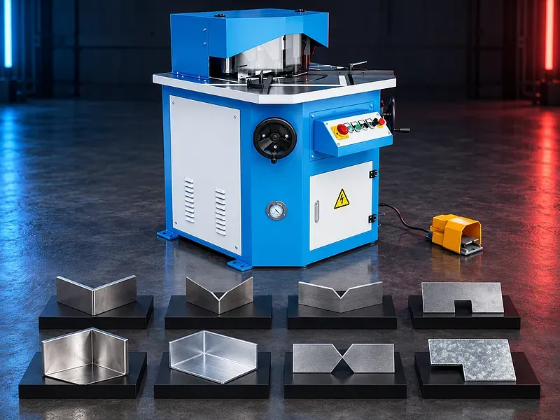
How angle notching works
The sheet is located on the working table and aligned to the required corner dimensions. A cutting stroke moves the upper blade arrangement past the lower blades so the selected corner section separates from the sheet.
Blade geometry, cutting sequence, clearance, overlap, material strength, thickness, sheet support, hold down action, and setup influence cutting load, edge condition, corner geometry, and repeatability.
Fixed angle notching
A fixed angle machine uses a blade arrangement designed around one stated notch angle. This configuration can suit repeated work when the required corner geometry matches the approved tool and machine range.
The actual angle, maximum notch dimensions, minimum practical notch, capacity by material, blade dimensions, adjustment method, and permitted use outside the nominal corner condition require verification.
Variable angle notching
A variable angle configuration allows the cutting blades or blade carriers to be adjusted within an approved angular range. It can support different corner geometries without changing the complete machine, but setup and capacity can vary with angle.
Minimum and maximum angle, notch dimensions at each angle, capacity derating, blade overlap, corner condition, setting scale, locking method, calibration, and change procedure must be confirmed from approved documentation.
Blade geometry and cutting clearance
Upper and lower blades need suitable geometry, material, hardness, straightness, edge condition, overlap, and clearance for the sheet and cutting method. Correct settings help control force, burr, deformation, and blade wear.
Blade clearance may be fixed or adjustable according to the design. The adjustment range, reference chart, measurement method, alignment, sharpening limits, reversal, grinding procedure, and replacement criteria require approved instructions.
Material and thickness capacity
Cutting capacity depends on material grade, tensile or shear strength, thickness, notch angle, blade geometry, cutting length, clearance, machine structure, and tool condition. Nominal thickness alone is not enough for selection.
Carbon steel, stainless steel, aluminum, copper, coated sheet, or other materials should only be listed after the exact capacity and edge requirements have been checked for the selected machine and material condition.
Notch dimensions and corner geometry
The drawing should define the corner angle, cut lengths on both sheet edges, internal corner condition, required relief, bend allowance, edge distance, hole relationship, and any material left for joining or finishing.
Maximum notch length, minimum dimensions, angle tolerance, corner radius or witness, intersection quality, straightness, and usable table references depend on the machine and setup and require verification.
Working table guides and stops
The table supports the sheet and provides reference surfaces for alignment. Adjustable guides, angle scales, stops, squaring arms, rulers, or digital indicators may help establish notch position when included and maintained.
Table dimensions, support load, surface condition, guide travel, scale resolution, stop arrangement, calibration, repeatability, locking, and compatibility with large or flexible sheets should be confirmed.
Sheet holding and support
Some machines use hold downs, clamps, pressure pads, or table features to stabilize the sheet near the cutting zone. Correct support can reduce lifting, movement, marking, and poor contact with the stops.
Hold down force, pad material, spacing, adjustment, sequence, marking risk, safe clearance, and suitability for thin or finished sheets depend on the machine configuration. Large sheets may need additional external support.
Hydraulic pneumatic and mechanical drive
The cutting stroke may be driven by hydraulic cylinders, pneumatic systems, mechanical transmission, or another approved arrangement. Each system has different force, speed, control, maintenance, utility, and duty characteristics.
Drive type, rated force, pressure, motor power, air demand, stroke control, speed, overload protection, oil or lubrication needs, noise basis, and duty pattern must be verified for the exact machine.
Controls and operator interface
Operation may use push buttons, a foot control, two hand control, mode selection, digital position indication, or programmed settings according to the safety design and machine configuration.
Control type, operating modes, cycle initiation, emergency stop, counter, angle indication, stored settings, diagnostics, permissions, backup, electrical enclosure, and optional functions require written confirmation.
Layout marking and setup
Setup should begin from the approved drawing, material specification, sheet thickness, corner dimensions, bend deduction, joint requirement, downstream process, and inspection plan. A trial piece can confirm the relationship between the drawing and machine references.
Manual marking, templates, stops, scales, digital indicators, or external measuring devices may be used according to the required tolerance. Every reference should be calibrated and protected from movement during production.
Production workflow
The process normally includes reviewing the drawing, confirming the sheet, checking blades and guards, setting the angle and clearance where applicable, positioning stops, supporting the sheet, completing a trial notch, measuring the result, correcting the setup, and releasing the batch.
Cut pieces and scrap should be controlled and removed through an approved method. The operator should not place hands in the cutting area or depend on visual alignment alone when dimensions require measurement.
Cut quality and inspection
Inspection may cover cut lengths, angle, squareness, corner intersection, burr height, rollover, edge deformation, straightness, surface marks, cracking, and the relationship to bends, holes, joints, or assembly features.
The quality plan should define tolerances, measuring equipment, datum, sampling, calibration, first part approval, deburring, correction method, nonconforming part handling, and traceability before production.
Burr edge condition and finishing
Burr and edge condition depend on material strength, thickness, blade sharpness, clearance, overlap, alignment, cutting direction, support, and wear. A clean appearance cannot be guaranteed for every material or setup.
Deburring, edge breaking, grinding, corner finishing, cleaning, or coating repair may be needed before bending, welding, painting, assembly, or safe handling. The required finish should be included in the process plan.
Blade maintenance and tool life
Blade condition should be inspected for wear, chipping, rounding, galling, corrosion, damage, alignment, and secure mounting. Suitable lubrication and cleaning may be required according to the machine and material.
Tool life depends on material, thickness, cutting length, clearance, setup, duty, blade material, sharpening quality, and maintenance. Low maintenance or long life should not be claimed without approved evidence.
Industrial applications
Potential applications include preparing sheet corners for boxes, cabinets, enclosures, trays, panels, ventilation products, electrical assemblies, metal furniture, appliance parts, ductwork, general fabrication, and supported repair work.
Application suitability depends on material, sheet size, corner design, bend sequence, joint method, finish, tolerance, batch mix, handling, safety, and the applicable fabrication standard.
How to choose the correct machine
Provide part drawings, material grades and strength, minimum and maximum thickness, sheet dimensions and mass, required angles, notch lengths, corner details, tolerances, edge requirements, quantities, batch sizes, and target output.
Also define fixed or variable angle needs, table and stop requirements, support and handling, drive preference, utilities, floor space, operator access, downstream bending or joining, inspection method, safety rules, and future work range.
Technical information to verify
Approved documents must confirm fixed or variable angle design, angle range, maximum notch dimensions, cutting capacity by material, blade length and geometry, blade clearance, stroke, cycles, table dimensions, stops, hold downs, drive system, motor power, hydraulic pressure or air demand, and controls.
Machine dimensions, weight, electrical supply, oil capacity, lubrication, noise test basis, guarding, safety functions, standard equipment, optional equipment, blade material, included tools, foundation, environmental limits, documentation, training, and acceptance method also require confirmation.
Safety and operating risks
Risks include blade contact, crushing, pinch points, unexpected cycle initiation, foot control misuse, sharp sheet edges, unstable large sheets, falling offcuts, ejected scrap, hydraulic or pneumatic pressure, electrical hazards, and unsafe handling.
The safety concept should include approved guards, protected controls, emergency stops, safe operating modes, controlled foot or two hand operation where applicable, sheet supports, scrap management, lockout procedures, inspection, training, personal protective equipment, and a documented risk assessment.
Installation and commissioning
Site preparation should cover delivery access, unloading, floor capacity, leveling, anchoring when required, electrical isolation, hydraulic oil or compressed air where applicable, lighting, working clearances, guards, sheet handling, scrap collection, and maintenance access.
Commissioning should include geometry, blade alignment, clearance, angle setting, table references, stop calibration, drive and control tests, pressure tests where relevant, safety validation, trial cuts, sample inspection, operator training, maintenance training, and document handover.
Maintenance and lifecycle support
Preventive maintenance should follow approved schedules for blades, holders, fasteners, guides, pivots, cylinders, seals, hoses, valves, filters, air preparation, lubrication, table surfaces, stops, scales, sensors, controls, guards, interlocks, and emergency systems.
Recommended blades, seals, hoses, filters, lubricants, drive parts, sensors, calibration devices, service tools, backups, technical support, training, inspection records, and documents should be agreed for the selected machine.
Limitations and publishing status
The supplied description does not prove precise or burr free cutting, high repeatability, low maintenance, long life, broad material capacity, increased productivity, or superior performance. These results depend on the exact machine, tools, setup, material, operator, and inspection.
The page needs an approved datasheet for the exact machine, verified material capacities, confirmed blade and angle configuration, approved images, technical review, staging review, and final content approval before publication.
Technical review and next step
Send part drawings, material grade and strength, sheet thickness and dimensions, notch angle and lengths, corner details, tolerances, edge requirements, quantities, downstream operations, handling method, utilities, and site layout for technical review.
The review should compare the application with approved machine data and identify the suitable notcher configuration, blade setup, stops, supports, inspection method, safety provisions, acceptance trial, installation, training, maintenance, and spare parts scope.
Questions we are asked
What is an angle notching machine?
It is a sheet metal cutting machine that removes a controlled corner section before bending joining enclosure fabrication or another downstream operation.
What is the difference between fixed and variable angle notching?
A fixed angle machine is built around one stated corner angle while a variable angle machine allows adjustment within an approved range. Capacity and notch size can change with the angle.
Can the machine notch different metals and thicknesses?
Only within the verified capacity for each material strength thickness notch geometry and blade condition. The exact range must be checked against approved data.
Does the machine guarantee burr free corners?
No. Burr and edge condition depend on material blade sharpness clearance overlap alignment support and wear. Finishing may still be required.
What information is needed for selection?
Provide the part drawing material strength thickness sheet size notch angle cut lengths corner details tolerances edge requirements quantities handling method utilities and downstream operations.
Tell us the part you need to make
An engineer reads every request. Usually the same working day.
Related
- CNC Hydraulic Press Brake CNC-controlled hydraulic press brakes for bending sheet metal components according to defined angles, dimensions and production requirements.
- CNC TUBE BENDING MACHINE CNC tube bending machines control the bending sequence to produce defined tube and pipe geometries. Selection depends on the material, section, diameter, wall thickness, bend radius, part geometry, accuracy, and production volume.
- CNC Gantry Plasma Cutting Machines A CNC gantry plasma cutting machine moves one or more cutting stations across a guided bridge to process suitable electrically conductive plate and supported profiles. The correct configuration depends on the material, thickness, plate size, part geometry, edge quality, bevels, secondary operations, extraction, automation, and required output.