

PNEUMATIC DRILLING AND TAPPING
Vertical Pneumatic Double Spindle Compound Machines
Vertical pneumatic double spindle compound machines combine supported drilling and tapping operations in one fixture based workstation. The arrangement can process suitable metal components such as fittings faucet parts handles valves and sanitary hardware when the spindle layout tooling fixture air system and cycle are matched to the part drawing
A double spindle compound machine uses two vertical machining heads so drilling and tapping can be arranged as sequential or dedicated operations without transferring the workpiece to separate standalone machines. Pneumatic cylinders may control head feed clamping indexing or other movements according to the verified design while spindle rotation may use a separate electric or mechanical drive. The correct machine depends on workpiece material hardness geometry datum surfaces hole diameter and depth thread size and pitch spindle spacing strokes speeds feeds tapping torque fixture design air quality pressure and flow cycle time inspection method and production volume. The exact function of each spindle must be confirmed for the model.
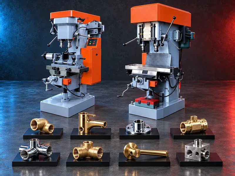
Double spindle compound concept
The workstation combines two vertical spindle heads around a common work area and fixture. One head may drill while another taps or each head may perform another supported operation according to the machine design.
Combining operations can reduce part handling and datum transfer but only when spindle positions travels tooling clearance and fixture sequence match the component.
Drilling operation
The drilling head creates the starting hole required by the drawing and the following tapping process. Drill diameter depth position runout point geometry speed feed coolant and chip evacuation affect hole quality.
The finished hole should provide the correct minor diameter straightness entry condition and bottom clearance for the thread standard and tap type.
Tapping operation
The tapping head forms or cuts the internal thread using a compatible tap holder speed feed reversal and depth control. Blind and through holes require different chip and clearance planning.
Thread size pitch class depth entry chamfer material chip behavior lubrication and tapping torque should be reviewed from the approved process.
Sequential and simultaneous cycles
Depending on the verified model the two heads may operate sequentially on one part sequentially on indexed positions or simultaneously on separate features or workpieces.
Simultaneous operation requires evidence of fixture stability power air capacity collision clearance control logic and safe chip management. It should not be assumed from the phrase double spindle alone.
Pneumatic feed and clamping
Compressed air may operate feed cylinders clamps slides stops or indexing devices. Regulators flow controls valves sensors and cushions may control movement and force according to the design.
Air pressure alone does not define feed force or speed. Cylinder size load flow restriction tooling resistance and adjustment affect the result.
Potential components and applications
Potential parts include supported brass fittings faucet bodies valve components door handles sanitary hardware connectors and other small or medium metal parts requiring repeat holes and internal threads.
Application suitability depends on casting or forging condition machining allowance access wall thickness datum quality clamping area tolerance finish and required output.
Materials and machinability
Potential materials may include supported brass grades steels stainless steels aluminum and other machinable metals when the spindle tooling fixture and cutting process are suitable.
Material grade hardness coating casting skin inclusions ductility and chip form should be confirmed. A general metal name does not prove that a drilling or tapping cycle is suitable.
Fixture and datum design
The fixture should locate the part from stable datum surfaces and resist drilling thrust tapping torque and pneumatic movement without distortion or part shift.
Locators clamps nests bushes stops and supports should allow loading chip escape tool access inspection and safe removal while preventing incorrect part orientation.
Spindle spacing and adjustability
The distance between spindle centerlines head adjustment range table movement and fixture positions determine which hole layouts can be reached.
The practical envelope is reduced by toolholders tap length drill length clamps part height and collision clearance. Exact head adjustment and locking require model verification.
Tooling and holders
Potential tooling includes drills center drills chamfers reamers taps collets drill chucks tapping holders length compensation holders torque control devices and compatible adapters.
Tool interface maximum size permitted speed runout overhang and holder function should match each spindle and operation. Tool change access and preset length should be included in the cycle plan.
Coolant lubrication and chips
Suitable cutting fluid or tapping lubricant may control heat reduce friction support tool life and improve finish when compatible with the material and process.
Chip evacuation is critical in blind holes and repeated cycles. Chips should not accumulate in fixtures locators pneumatic slides sensors guards or electrical components.
Thread quality and inspection
Acceptance may include hole diameter depth position perpendicularity thread size pitch class depth entry condition and functional fit according to the drawing and thread standard.
Inspection may use calibrated plug gauges depth methods position fixtures optical measurement or mating parts according to the approved quality plan.
Cycle control and productivity
The cycle may include part loading confirmation clamping drilling dwell return indexing tapping reversal unclamping and unloading according to the control logic.
Actual output depends on loading fixture access drilling tapping tool life chip clearing inspection and downtime. Published cycle time or production claims require a verified part trial.
How to choose the correct machine
Provide component drawings material grade hardness part dimensions and weight hole diameters depths positions thread sizes pitches depths quantities batch size duty pattern fixture concept and target output.
Selection should consider each spindle function spacing adjustment stroke speed feed motor power tapping torque holder interface table and fixture area pneumatic clamp control coolant sensors guards air supply floor space and service access.
Technical information to verify
The approved exact model source must confirm manufacturer brand model machine layout function of each spindle spindle spacing and adjustment drilling and tapping capacities by material and conditions speed ranges strokes feeds motor power and tapping reversal method.
It must also confirm holder interfaces table dimensions fixture provision pneumatic pressure flow and filtration controls sensors coolant lubrication electrical supply dimensions weight accuracy test basis cycle time basis guards safety devices included tooling and options.
Compressed air requirements
The air system should provide the verified pressure flow cleanliness dryness and connection size at the machine during the complete cycle. A regulator filter water separator lubricator where required and safe isolation may be needed.
Low pressure restricted flow water oil contamination or leaks can cause slow movement inconsistent clamping tool breakage or cycle faults.
Safety requirements
The risk assessment should address rotating drills and taps automatic spindle feed pneumatic clamps pinch and crush zones tool breakage sharp chips ejected parts stored air pressure coolant noise and electrical hazards.
Guards interlocks emergency stops secure fixtures two hand or protected cycle start where required safe loading zones air isolation pressure release operating instructions training personal protective equipment and maintenance controls must follow approved documentation and site requirements.
Installation maintenance and support
Site planning should cover a stable foundation or bench leveling electrical supply grounding clean regulated compressed air coolant or lubrication lighting chip collection tooling storage operator access and maintenance clearance.
Preventive maintenance should cover spindles bearings belts or drives slides cylinders valves air preparation clamps fixtures toolholders coolant lubrication sensors controls guards fasteners alignment and leak checks. Supply scope training spare parts warranty and service commitments require approved confirmation.
Limitations and alternative processes
A vertical pneumatic double spindle machine is not automatically suitable for every part material hole thread spacing depth tolerance duty cycle or output target. Product changes may require new fixtures tools and head adjustments.
Separate drilling and tapping machines a rotary transfer machine CNC machining center dedicated multi spindle machine tapping center or another process may be more suitable for complex geometry flexible batches tighter positioning or higher volume.
Technical review and next step
Send component drawings and samples with material hardness hole and thread data datum surfaces quantities fixture concept current process air and electrical supply and target output.
SAKKARY MACHINERY will review process sequence spindle layout fixture tooling feeds tapping control inspection utilities safety alternatives and information that still requires manufacturer verification.
Questions we are asked
What is a vertical pneumatic double spindle compound machine?
It is a fixture based workstation with two vertical spindle heads arranged to perform supported drilling tapping or other defined operations on metal parts.
Can it drill and tap in one setup?
Potentially yes when one spindle is configured for drilling and the other for tapping and the fixture positions and sequence match the part.
Can both spindles operate at the same time?
Only if the verified machine control fixture power air capacity tooling clearance and safety design support simultaneous operation.
Which parts can it process?
Potential parts include supported brass fittings faucet parts handles valve components sanitary hardware connectors and other parts requiring repeat holes and threads.
What does the pneumatic system control?
It may control spindle feed clamping slides stops or indexing depending on the design. The exact function requires model verification.
What information is required for selection?
Provide part drawings material hardness hole diameters depths positions thread sizes pitches depths quantities fixture concept air and electrical supply and target output.
Tell us the part you need to make
An engineer reads every request. Usually the same working day.
Related
- Heavy-Duty Gap-Bed Conventional Lathes Heavy-duty conventional lathes for turning large-diameter, long, and heavy rotational components. The gap-bed design provides additional swing near the headstock for suitable short workpieces.
- Gantry Type Milling Machine A gantry-type milling machine provides an open working area for machining suitable large or heavy components. Selection depends on workpiece dimensions, weight, material, required operations, tolerances, finish, and production requirements.
- Boring Machine for Workshop Machining A boring machine for drilling, enlarging, finishing, and aligning suitable holes in individual parts and small production batches. The correct model depends on workpiece size, material, hole diameter, depth, tolerance, surface finish, setup, tooling, and required output.