

UNIVERSAL GRINDING MACHINES
Universal Grinding Machine
A universal grinding machine for supported tool, cutter, saw blade, surface, and selected cylindrical grinding work using the correct attachments and setup. Final suitability depends on the component, material, grinding operation, wheel, workholding, accuracy, finish, batch size, and verified machine configuration.
A universal grinding machine combines an adjustable grinding head, work supports, tables, and interchangeable fixtures to perform several supported grinding tasks from one machine platform. Its value comes from configuration flexibility rather than a single fixed production operation. The uploaded catalog image shows a universal grinding machine with several grinding and workholding attachments. The operations, capacities, wheel data, travels, motors, accuracy, and list of standard accessories shown or implied by the image require confirmation from an approved official catalog and current quotation before publication.
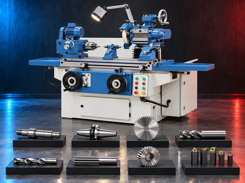
Universal grinding concept
A universal grinding machine uses adjustable heads, tables, centers, chucks, fixtures, and wheel arrangements to adapt the machine to different supported grinding operations. Each configuration requires a defined setup and verified clearances.
The machine should be selected from the actual workpieces and operations, not from the word universal alone. Attachment availability, capacity, rigidity, spindle condition, wheel selection, and operator skill determine practical capability.
Tool and cutter grinding
With suitable verified attachments, the machine may support grinding or resharpening of selected drills, milling cutters, reamers, lathe tools, and other cutting tools according to their geometry.
Tool type, flute count, helix, rake, relief, diameter, length, material, coating, edge condition, wheel access, indexing, and inspection method must be reviewed before confirming suitability.
Saw blade grinding
The uploaded image presents saw blade grinding as a possible application. This operation normally requires a suitable blade support, indexing or dividing arrangement, wheel profile, tooth geometry setup, and safe clearance.
Blade diameter range, tooth pitch, tooth form, material, carbide or steel condition, indexing accuracy, wheel specification, and attachment scope require confirmation from official model documents.
Surface and face grinding
A compatible table, vise, fixture, or surface grinding attachment may support selected flat faces, shoulders, tool surfaces, and small components when the verified machine geometry and wheel access permit the operation.
Work size, magnetic or mechanical holding, travel, grinding area, flatness, finish, stock allowance, spark out, cooling, and inspection need a defined process plan.
External and internal cylindrical grinding
Centers, a chuck, workhead, tailstock, internal grinding spindle, rests, or other attachments may support selected external or internal cylindrical grinding work according to the verified configuration.
Work diameter, length, weight, center condition, bore diameter and depth, speed, taper, runout, wheel access, support, dressing, and achievable result must be checked for the exact setup.
Grinding heads spindles and movement
The machine image shows several adjustable assemblies, but the exact spindle arrangement and movement ranges cannot be approved from a photograph. Head rotation, tilt, height, table travel, slide travel, workhead speed, and internal spindle limits require official data.
Every setup should confirm wheel and fixture clearance across the complete travel, including approach, grinding, spark out, retraction, dressing, and loading positions.
Workholding centers chucks and fixtures
Potential workholding may include centers, chucks, collets, vises, dividing heads, supports, rests, mandrels, arbors, and dedicated fixtures compatible with the workpiece and operation.
The setup must locate the part from suitable datums and resist grinding forces without distortion or slip. Center height, alignment, clamping, runout, support, balance, and safe loading should be verified.
Grinding wheel selection
Wheel selection should consider abrasive type, grit size, grade, structure, bond, shape, dimensions, speed rating, work material, hardness, stock removal, finish, contact area, cooling, and dressing method.
Only approved wheels within the spindle speed and dimensional limits should be used. Wheel markings, storage, inspection, mounting, blotters or flanges where applicable, tightening, guarding, and replacement criteria must follow approved instructions.
Wheel dressing and profiling
Dressing restores cutting action and corrects wheel shape. Profiling may be needed for tool geometry, saw teeth, radii, angles, shoulders, or other supported forms.
Dresser type, position, traverse, depth, frequency, coolant, compensation, wheel loss, profile verification, and safe access should be defined for the operation and compatible attachment.
Wheel balancing and vibration control
Balancing can reduce vibration and support surface condition, spindle life, wheel life, and process stability. Requirements depend on wheel dimensions, speed, grade, mounting system, and grinding duty.
The image lists a balancing stand, but its supply status and specification require confirmation. Static or dynamic balancing method, arbor, flange condition, wheel inspection, and acceptance should follow approved procedures.
Coolant dust and spark control
Coolant may help control heat, wash the contact zone, preserve surface condition, and reduce loading when compatible with the wheel, material, and operation. Some tool grinding tasks may use another approved method.
Grinding dust, mist, sparks, and swarf require process specific containment and extraction. The image shows a coolant device and dust extractor in an accessory list, but exact equipment, airflow, filtration, and inclusion require verification.
Grinding quality and inspection
Acceptance may cover dimensions, diameter, taper, runout, straightness, roundness, flatness, angle, tooth or tool geometry, edge condition, surface finish, burns, cracks, chatter, and functional fit.
Inspection may use calibrated micrometers, indicators, height or angle measurement, profile projectors, optical systems, surface roughness instruments, gauges, templates, runout fixtures, and crack inspection where required.
Setup changeover and operator skill
A universal machine can change between applications, but each changeover may require different attachments, alignment, wheel selection, dressing, guards, workholding, process data, and inspection.
Productivity, accuracy, repeatability, setup time, and tool quality depend strongly on operator training, documented setup sheets, fixture condition, wheel care, machine condition, and controlled first part approval.
How to choose the correct machine
Provide drawings or samples, material and hardness, tool or part type, diameters, lengths, bores, tooth or flute geometry, stock allowance, tolerances, finish, quantities, batch sizes, current process, and target output.
Selection should review required grinding modes, attachments, wheel dimensions, spindle speeds, table and head travels, workholding, centers, chucks, dividing functions, internal grinding, dressing, balancing, cooling, extraction, guarding, inspection, utilities, and future work.
Technical information to verify
An approved official technical source must confirm the intended grinding operations, machine layout, table dimensions and travels, head movements, spindle arrangements, spindle speeds, workhead capacity, center height, distance between centers, and internal grinding limits.
It must also confirm wheel dimensions and speed limits, motors, electrical supply, coolant, extraction, guards, accuracy and test conditions, dimensions, weight, foundation, manuals, included standard accessories, optional accessories, consumables, and current supply scope.
Safety and operating risks
The risk assessment should cover wheel burst, contact with rotating wheels and workpieces, sparks, hot particles, dust, mist, entanglement, workpiece ejection, crushing points, sharp tools, dressing hazards, manual handling, electrical hazards, and maintenance isolation.
Required controls may include wheel guards, work supports, correct flanges, wheel inspection, speed checks, spark containment, extraction, coolant management, secure workholding, eye and face protection, hearing and respiratory protection where required, training, and documented lockout procedures.
Installation maintenance and lifecycle support
Site planning should cover floor capacity, leveling and anchoring, electrical supply, lighting, coolant and drainage, dust extraction, ventilation, fire precautions, wheel and attachment storage, lifting, loading access, maintenance clearance, and operator training.
Preventive maintenance should follow approved manufacturer documents for grinding spindles, workhead, bearings, belts, slides, screws, lubrication, coolant, extraction, guards, electrical controls, alignment, attachment interfaces, wheel mounting components, and calibration.
Limitations and alternatives
A universal grinder offers flexibility but may require longer setup and more operator skill than a dedicated production grinder. It may not suit high volume automated work, large components, heavy stock removal, or demanding tolerances outside the verified configuration.
Depending on the work, alternatives may include a dedicated tool and cutter grinder, cylindrical grinder, internal grinder, surface grinder, saw blade grinder, CNC grinding machine, or specialist sharpening system.
Technical review and next step
Send component or tool drawings, samples, material and hardness, geometry, stock allowance, tolerance, finish, annual and batch quantities, current process, target output, site utilities, floor plan, and preferred accessories for technical review.
The technical review will compare the application with approved machine documentation and identify the supported grinding mode, attachments, wheels, workholding, dressing, balancing, cooling, extraction, inspection, installation needs, and any sample grinding requirement.
Questions we are asked
What is a universal grinding machine?
It is a configurable grinding machine that uses adjustable heads tables workholding and attachments to support several defined grinding operations.
Can the machine grind tools and saw blades?
The uploaded image presents tool and saw blade grinding as applications. Exact tool families blade ranges attachments and setup requirements need official technical verification.
Can it perform surface and cylindrical grinding?
Potentially when the verified attachments travels workholding wheel access and machine capacity support the specific part and required result.
Are all accessories shown included as standard?
Not confirmed. The image contains an accessory list but the current standard and optional supply must be verified through an approved catalog and quotation.
How is the grinding wheel selected?
Selection depends on abrasive grit grade structure bond shape dimensions speed work material stock removal finish cooling and dressing method.
What information is required for selection?
Provide drawings or samples material hardness geometry stock allowance tolerance finish quantities current process target output utilities floor plan and required attachments.
Tell us the part you need to make
An engineer reads every request. Usually the same working day.
Related
- Heavy-Duty Gap-Bed Conventional Lathes Heavy-duty conventional lathes for turning large-diameter, long, and heavy rotational components. The gap-bed design provides additional swing near the headstock for suitable short workpieces.
- Gantry Type Milling Machine A gantry-type milling machine provides an open working area for machining suitable large or heavy components. Selection depends on workpiece dimensions, weight, material, required operations, tolerances, finish, and production requirements.
- Boring Machine for Workshop Machining A boring machine for drilling, enlarging, finishing, and aligning suitable holes in individual parts and small production batches. The correct model depends on workpiece size, material, hole diameter, depth, tolerance, surface finish, setup, tooling, and required output.