

CONTROLLED PRESSING FORCE
Hydraulic Press Machines
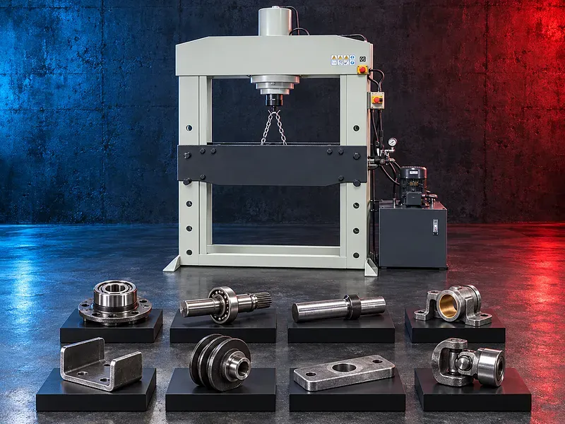
Hydraulic presses apply controlled linear force for suitable straightening pressing fitting assembly disassembly extraction and forming tasks. The correct workshop or production press depends on the required force stroke working space frame tooling support control method safety measures and part handling plan.
A hydraulic press converts fluid pressure into force through a cylinder and ram. The workpiece and tooling are positioned inside the frame so the ram can apply a controlled load along the intended line of action. Depending on the verified configuration the press may be used for straightening shafts and plates pressing bearings or bushes fitting components removing pins or rollers compacting and selected forming operations. A press should never be selected from rated tonnage alone. Part geometry material condition required load load direction stroke daylight bed area support spacing tooling stability off center allowance speed cycle frequency pressure control utilities guarding and operator access must be checked for the exact model and task.
Hydraulic pressing principle
The hydraulic power unit supplies pressurized fluid to the cylinder so the ram advances and applies force through the tooling to the supported workpiece. The ram then stops holds or returns according to the control arrangement.
Available force changes with hydraulic pressure and cylinder area while actual task force also depends on friction geometry deformation and tooling. Rated capacity must not be exceeded.
Straightening operations
Potential straightening tasks include suitable shafts bars plates sections weldments and machine parts when the workpiece is correctly supported and the deformation can be controlled.
Support spacing load position material condition springback local stress and measurement method should be planned. Incorrect support or excessive force can buckle crack mark or eject the part.
Press fitting and assembly
Potential tasks include installing suitable bearings bushes sleeves pins gears and other interference fit components with the correct adapters and alignment.
Fit allowance surface condition lubrication lead in geometry component temperature support and maximum insertion force should follow the approved engineering requirement.
Disassembly and extraction
A hydraulic press may remove suitable pins shafts bushes bearings rollers or assembled parts when safe support and extraction tooling are provided.
Unknown retention methods corrosion hidden fasteners stored energy brittle components and sudden release create serious risk. The assembly must be assessed before force is applied.
Forming and compression tasks
Selected bending flanging embossing punching compacting swaging or forming tasks may be possible only when the press frame stroke speed control tooling and safety system are designed for the application.
A general workshop press should not be assumed suitable for production forming dies blanking impact work or high cycle operation without manufacturer approval.
Frame configurations
Common arrangements may include H frame C frame four column straight side bench floor standing or mobile workshop designs. Frame construction affects access rigidity load path off center capability and guarding.
Open access can improve handling but may reduce support or raise exposure. The exact frame rating and permitted loading pattern require model verification.
Ram stroke daylight and working area
The usable setup must fit between the ram and bed with enough space for the workpiece tooling supports and safe loading. Stroke must cover approach working movement and withdrawal without bottoming the cylinder.
Daylight bed width distance between uprights ram to bed geometry and adjustable bed positions all affect the practical envelope.
Tooling supports and load path
Press plates V blocks mandrels drifts adapters punches dies fixtures and supports should be engineered for the force contact shape material and operation. Makeshift brittle or damaged supports are unsafe.
The load should pass through the intended ram workpiece support bed and frame path with stable contact and minimal eccentricity. Tooling must not tilt slip or eject under load.
Force pressure and position control
Depending on the verified model the operator may control advance speed pressing speed return dwell pressure or position. Pressure gauges switches valves or digital controls may be provided.
Hydraulic pressure indication does not directly prove force at the part unless the cylinder area calibration losses tooling and measurement method are defined. A load cell may be required for verified force.
Manual electric and powered operation
Small workshop presses may use hand or foot powered pumps while larger machines may use electric hydraulic power units and directional controls. Some designs provide two hand controls pedals or automatic sequences.
Operation type should be selected from force speed cycle frequency control safety ergonomics utilities maintenance and task risk. Foot controls require particular guarding and safe hand positioning.
Quality and inspection
Acceptance may include straightness alignment insertion depth extraction condition final dimensions angular change surface condition absence of cracks and functional fit according to the approved requirement.
The inspection plan should define datum method instruments checkpoints allowable springback and whether force displacement or pressure records are required.
How to choose the correct press
Provide the component drawing material condition dimensions weight operation required force or engineering calculation stroke working height tooling support layout tolerance quantity cycle frequency and target output.
Selection should consider rated force frame type permitted off center load stroke daylight bed size upright spacing ram size speed control bed adjustment hydraulic system gauge guarding utilities floor space lifting and service access.
Technical information to verify
The approved exact model source must confirm manufacturer brand model rated force test basis frame type maximum pressure stroke daylight bed and ram dimensions upright spacing adjustable bed capacity advance pressing and return speeds motor and pump data.
It must also confirm permitted off center load control modes pressure indication accuracy hydraulic fluid electrical supply dimensions weight foundation mounting tooling guards safety devices included equipment and options.
Safety requirements
The risk assessment should address crushing trapping ejected tooling sudden part release stored hydraulic energy hose failure falling beds heavy handling sharp edges noise hot fluid and electrical hazards.
Engineered tooling secure supports guards light curtains or interlocks where required two hand controls safe foot control arrangements pressure relief emergency stops isolation blocked ram procedures training and personal protective equipment must follow approved documentation and site requirements.
Installation and commissioning
Site planning should cover floor capacity anchoring leveling lifting route electrical supply grounding hydraulic fluid temperature ventilation lighting guarding workpiece handling tooling storage and maintenance access.
Commissioning should verify assembly fasteners fluid level leaks hose condition pump rotation pressure relief gauge function ram alignment bed locking controls safety devices no load movement and an approved trial operation.
Maintenance and lifecycle support
Preventive maintenance should cover hydraulic fluid filters hoses fittings seals cylinder rod pump valves pressure gauge relief devices frame welds fasteners bed pins guides controls guards and periodic alignment checks.
The exact supply scope installation training oil and filter requirements maintenance intervals spare parts warranty and service commitments require confirmation in the approved technical and commercial offer.
Limitations and alternative processes
A hydraulic press is not automatically suitable for every straightening fitting extraction forming material force speed accuracy or cycle requirement. Unstable brittle explosive hot or poorly supported work can be unsafe.
A mechanical press servo press arbor press dedicated bearing installer puller straightening machine press brake roll or custom fixture may be more suitable depending on the operation.
Technical review and next step
Send the component drawing with material condition dimensions weight operation load calculation stroke setup tooling support tolerance quantity duty cycle handling plan utilities and target output.
SAKKARY MACHINERY will review required force frame and envelope tooling load path control inspection handling utilities safety alternatives and information that still requires manufacturer verification.
Questions we are asked
What is a hydraulic press?
It is a machine that converts hydraulic pressure into controlled linear force through a cylinder and ram for supported pressing operations.
Which operations can it perform?
Potential tasks include straightening press fitting assembly disassembly extraction compression and selected forming when the machine tooling and safety system are suitable.
Is rated tonnage enough to select a press?
No. Stroke daylight bed area frame type load direction tooling off center allowance speed duty and safety must also be reviewed.
Can a hydraulic press remove bearings or rollers?
Potentially yes when the assembly retention method required force support extraction tooling and sudden release risk are understood and controlled.
Can the pressure gauge confirm pressing force?
Not automatically. Force confirmation depends on cylinder area calibration hydraulic losses tooling and the measurement method. A load cell may be required.
What information is required for selection?
Provide the drawing material condition dimensions weight operation force calculation stroke setup tooling support tolerance quantity cycle frequency and target output.
Tell us the part you need to make
An engineer reads every request. Usually the same working day.
Related
- Heavy-Duty Gap-Bed Conventional Lathes Heavy-duty conventional lathes for turning large-diameter, long, and heavy rotational components. The gap-bed design provides additional swing near the headstock for suitable short workpieces.
- Gantry Type Milling Machine A gantry-type milling machine provides an open working area for machining suitable large or heavy components. Selection depends on workpiece dimensions, weight, material, required operations, tolerances, finish, and production requirements.
- Boring Machine for Workshop Machining A boring machine for drilling, enlarging, finishing, and aligning suitable holes in individual parts and small production batches. The correct model depends on workpiece size, material, hole diameter, depth, tolerance, surface finish, setup, tooling, and required output.