

VERSATILE CONVENTIONAL MILLING
Conventional Milling Machines Vertical and Horizontal
Conventional vertical and horizontal milling machines support suitable milling drilling slotting and surface machining tasks with direct operator control. The two spindle arrangements provide flexibility for precision workshop work and heavier cutting applications when the selected model tooling setup and duty are correctly matched
A conventional milling machine removes material with a rotating cutter while the operator positions the workpiece through the table axes and controls spindle speed feed and depth of cut. Vertical machines provide direct access for face milling end milling drilling slots pockets and setup work. Horizontal machines support arbor mounted cutters for side milling slab milling gangs slots and other suitable operations. Some machines provide one configuration while universal or combined designs may support both. The correct choice depends on the component drawing material hardness dimensions weight machining envelope features tolerances finish batch size tooling workholding operator skill duty cycle and available workshop utilities.
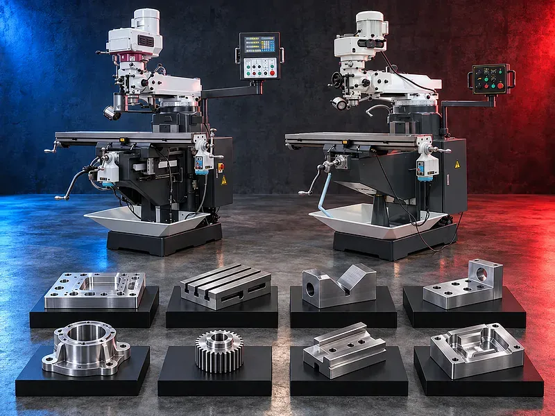
Conventional milling concept
The operator sets the workpiece datum selects and mounts the cutter adjusts spindle speed and feed and moves the supported machine axes to create the required surface or feature.
Manual control provides flexibility for repair work toolroom tasks prototypes individual parts and varied small batches but the result depends strongly on setup method machine condition and operator practice.
Vertical milling configuration
A vertical spindle presents the cutter above the workpiece and can provide clear access for face milling end milling drilling reaming boring slots shoulders steps pockets and selected angular features when supported by the machine.
Head movement quill functions spindle taper speed range feeds and tilt or swivel capability vary by model and must be verified before specifying an operation.
Horizontal milling configuration
A horizontal spindle can carry arbor mounted cutters supported by an overarm and arbor support according to machine design. Potential operations include slab milling side milling straddle milling gang milling deep slots and selected form work.
Horizontal milling may support heavier cuts when the verified machine rigidity spindle torque arbor cutter workholding and setup are suitable. It should not be described as heavy duty without model evidence.
Universal and combined arrangements
Universal or combined machines may provide a swiveling table vertical attachment separate vertical head or another method of accessing both vertical and horizontal work. Exact construction and included equipment are model specific.
Changing configuration requires correct mounting alignment lubrication guarding tooling clearance and verification of spindle direction speed and support.
Potential milling and drilling operations
Potential work includes flat and side surfaces shoulders steps slots keyways pockets profiles angles drilling reaming countersinking counterboring light boring and selected tapping when supported by the exact machine and tooling.
Every operation should be reviewed for material feature size stock allowance tolerance finish cutter engagement spindle load axis travel feed chip evacuation coolant and inspection access.
Machine structure and guideways
The base column knee saddle table heads spindles overarm guideways screws and drive systems form the load path of the machine. Rigidity geometry backlash lubrication and thermal condition influence accuracy and finish.
Machine size weight or appearance alone does not prove capacity. Foundation leveling gib adjustment spindle condition guide wear locks and preventive maintenance must be considered.
Table movement and setup envelope
The table and supporting axes position the workpiece through longitudinal cross and vertical movement according to machine design. Setup must remain within verified travels table area load spindle reach and clearance.
Workpiece height fixture stack cutter arbor overhang indexers rotary tables angle plates and inspection access can reduce the practical machining envelope and increase collision risk.
Tooling and cutter selection
Potential tooling includes face mills end mills shell mills slab mills side and face cutters slot drills keyway cutters form cutters drills reamers boring heads arbors collets chucks and compatible holders.
Cutter material geometry diameter width tooth count mounting interface permitted speed and cutting data should match the workpiece material operation machine power spindle taper arbor support and finish requirement.
Workholding and reference control
Workholding may include machine vises clamps parallels angle plates V blocks rotary tables dividing heads fixtures and supports selected for the component geometry cutting force table load and datum plan.
The setup should prevent movement lifting distortion and chatter while preserving cutter clearance chip flow axis travel and access for measurement.
Speeds feeds and cutting strategy
Spindle speed table feed depth and width of cut cutter engagement coolant and pass sequence should suit the material cutter machine rigidity available power finish and tooling supplier guidance.
Excessive load poor support long tool or arbor overhang weak clamping backlash or trapped chips can reduce tool life finish accuracy and safety.
Accuracy and inspection
Acceptance may include dimensions flatness straightness parallelism perpendicularity slot width and depth hole position angular features surface finish and fit with mating parts according to the drawing.
Finished accuracy depends on machine geometry backlash spindle runout head alignment thermal behavior workholding cutter condition datum transfer operator method and calibrated inspection equipment.
How to choose the correct machine
Provide component drawings with material hardness dimensions weight features machining envelope stock allowance tolerances finish quantities batch size setup constraints and target output.
Selection should consider vertical horizontal or combined configuration table dimensions and load travels spindle taper speed and power feeds quill arbor and support universal table DRO coolant lubrication tooling accessories guards utilities and floor space.
Technical information to verify
The approved exact model source must confirm manufacturer brand model machine configuration table size table load travels spindle taper speed ranges spindle power feed ranges quill data arbor dimensions and milling or drilling capacities with test conditions.
It must also confirm head and table movement DRO power feeds rapid traverse coolant lubrication guideway type accuracy test standard electrical supply dimensions weight foundation included tooling guards safety devices and optional equipment.
Safety requirements
The risk assessment should address rotating cutters arbors and spindles entanglement sharp and hot chips tool breakage ejected workpieces loose keys axis movement pinch points coolant lifting and electrical hazards.
Guards emergency stops cutter and arbor checks secure workholding safe setup zones operating instructions training personal protective equipment and maintenance controls must follow approved documentation and site requirements.
Installation maintenance and support
Site planning should cover foundation or floor capacity leveling lifting route electrical supply grounding coolant lubrication chip management lighting ventilation tooling storage inspection space and maintenance access.
Preventive maintenance should cover guideways screws nuts gibs spindles gears belts feeds locks coolant lubrication electrical controls guards geometry and alignment. Supply scope training spare parts warranty and service commitments require approved confirmation.
Limitations and alternative processes
A conventional milling machine is not automatically suitable for every material geometry size weight tolerance finish duty cycle batch volume or productivity target. Complex repeated features may depend too heavily on operator time and manual positioning.
A drilling machine boring machine bed mill CNC milling machine CNC machining center or another process may be more suitable for larger parts tighter repeatability complex geometry automation or higher volume.
Technical review and next step
Send the component drawings with material hardness dimensions weight required features stock allowance tolerances finish quantities setup constraints available tooling duty pattern and target output.
SAKKARY MACHINERY will review vertical and horizontal process options machine envelope table spindle arbor tooling workholding sequence inspection utilities safety alternatives and information that still requires manufacturer verification.
Questions we are asked
What is a conventional milling machine?
It is a manually controlled machine that uses rotating cutters and movable axes to produce supported surfaces slots holes and other machined features.
What is the difference between vertical and horizontal milling?
Vertical milling places the cutter above the workpiece for accessible precision and setup work while horizontal milling uses a horizontal spindle and may carry supported arbor cutters for suitable side surface and slot operations.
Is horizontal milling always suitable for heavy cutting?
No. Heavy cutting depends on verified rigidity torque power arbor support tooling workholding material and duty cycle for the exact model.
Can one machine provide both configurations?
Some universal or combined machines can support both through separate heads attachments or table arrangements. The exact configuration and included equipment must be verified.
Which operations can be performed?
Potential operations include face and side milling slots keyways shoulders steps drilling reaming countersinking boring and selected angular or profile work when supported by the machine and setup.
What information is required for selection?
Provide drawings material hardness dimensions weight features tolerances finish quantities setup constraints and target output.
Tell us the part you need to make
An engineer reads every request. Usually the same working day.
Related
- Heavy-Duty Gap-Bed Conventional Lathes Heavy-duty conventional lathes for turning large-diameter, long, and heavy rotational components. The gap-bed design provides additional swing near the headstock for suitable short workpieces.
- Gantry Type Milling Machine A gantry-type milling machine provides an open working area for machining suitable large or heavy components. Selection depends on workpiece dimensions, weight, material, required operations, tolerances, finish, and production requirements.
- Boring Machine for Workshop Machining A boring machine for drilling, enlarging, finishing, and aligning suitable holes in individual parts and small production batches. The correct model depends on workpiece size, material, hole diameter, depth, tolerance, surface finish, setup, tooling, and required output.