

BENDING CUTTING AND PUNCHING
Compact Busbar Bending Cutting and Punching Machines
Compact busbar processing machines combine supported bending cutting and punching functions for copper and aluminum busbars in one movable workshop solution. The correct machine depends on busbar material width thickness feature dimensions bend geometry hole requirements tooling power supply duty pattern and required output.
A compact busbar machine provides separate work units for bending cutting and punching so operators can prepare electrical busbar components without moving between three independent machines. A wheeled base may support relocation within a suitable workshop or controlled site area when the floor route stability power cable and operating clearance are safe. The supplied description refers to single phase 220 volt power high production low noise and broad site use. These are model specific claims and require verification from the approved electrical and technical documentation. Capacity cutting quality bend accuracy punch range mobility and productivity must be checked against the actual busbar program.
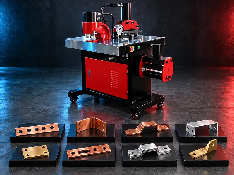
Three function processing concept
The machine places bending cutting and punching functions in one compact platform. Each unit uses dedicated tooling and controls suited to its operation.
Combining the stations may reduce internal movement and floor space but does not remove the need for setup measurement deburring inspection and safe material handling.
Suitable busbar materials
Potential materials include supported copper and aluminum busbar grades used in electrical distribution assemblies. Conductivity alloy temper hardness surface coating and material condition affect cutting punching bending and final electrical performance.
Material identity should be controlled. A general description such as copper or aluminum does not prove that every width thickness bend or hole is suitable.
Busbar cutting unit
The cutting unit shears the busbar to the required length using matched blades and a stable support. The part should be positioned squarely and held clear of the danger zone.
Acceptance may include cut length squareness edge condition burr height deformation and absence of cracks. Blade clearance condition alignment and material affect the result.
Busbar punching unit
The punching unit creates supported holes or slots using compatible punches and dies. Feature size shape pitch edge distance and orientation should follow the electrical and mechanical drawing.
Punch to die clearance alignment sharpness stripping and work support influence hole quality burrs distortion tool life and safety.
Busbar bending unit
The bending unit forms the busbar to the required angle offset or shape using approved punches dies or bending attachments. The setup should support the bar and control its orientation.
Bend radius angle straight lengths springback surface marking cracking and conductor spacing should be checked. Tool geometry must match the busbar dimensions and required bend.
Flat edge and offset bending
Potential operations may include flatwise bending edgewise bending offsets steps or twists only when the verified machine tooling and busbar section support them.
Edge bending twisting and close offsets can require special tooling and may create higher deformation or marking risk. These capabilities should not be assumed from general bending capacity.
Tooling selection and change
Cutting blades punches dies bending tools guides and stops should match the machine busbar material dimensions and feature. Tool identification should be clear and controlled.
Tools should be clean complete sharp undamaged correctly aligned and secured. Mixed incorrect or worn tooling can damage the part machine and operator.
Measurement stops and setup
Length stops rulers gauges angle references or digital displays may support repeatable positioning according to the model. Their resolution does not by itself prove part accuracy.
Datum selection bar straightness end condition stop contact tool clearance operator method and inspection all affect the finished dimensions.
Electrical panel and switchgear applications
Potential products include busbar links feeders connections and formed conductors for distribution boards switchboards switchgear control cabinets and related electrical assemblies.
Electrical design current rating phase spacing insulation clearance creepage temperature rise plating joint preparation and applicable standards remain the responsibility of the approved engineering design.
Mobility and on site use
A compact wheeled base may help move the machine between controlled work areas. Wheels do not make every construction site suitable for operation.
Floor level strength slope thresholds cable route weather dust moisture lighting security wheel brakes and operating clearance should be checked before relocation or use.
Power supply and utilities
The exact voltage phase frequency current protective device cable plug grounding and hydraulic oil requirements must match the approved machine documentation and site supply.
The stated single phase 220 volt supply is unverified for the exact model and should not be published until the nameplate datasheet and local electrical review agree.
Quality and inspection
Inspection may include material identity length width thickness cut squareness hole size slot size position edge distance bend angle radius offset overall geometry burrs cracks surface marks and fit in the assembly.
The quality plan should define measuring instruments gauges sample frequency first piece approval traceability and disposition of nonconforming parts.
How to choose the correct machine
Provide busbar material grade condition width thickness length drawings hole and slot sizes bend radii angles offsets tolerances quantities batch size site needs power supply and target output.
Selection should consider cutting capacity punching force punch range throat depth bending force angle and tooling flat or edge bend options work height control stops hydraulic system electrical supply wheel arrangement floor space and service access.
Technical information to verify
The approved exact model source must confirm manufacturer brand model machine configuration supported materials maximum busbar width and thickness for each operation cutting capacity punching force maximum hole and slot dimensions throat depth bending capacity radius and angle range.
It must also confirm hydraulic pressure motor power voltage phase frequency controls accuracy test basis cycle times noise test basis dimensions weight wheels brakes oil requirements included tools guards safety devices and optional tooling.
Productivity and workflow
Actual output depends on drawing review material staging measuring cutting punching bending tool changes deburring cleaning marking inspection and movement between units rather than machine cycle time alone.
Batch work may benefit from planned operation sequence dedicated tools stops gauges first piece approval and separation of finished and nonconforming parts.
Safety requirements
The risk assessment should address cutting and punching crush zones bending movement sharp busbar edges tool breakage ejected slugs heavy bars hydraulic pressure wheel movement electrical hazards and manual handling.
Guards interlocks emergency stops secure tooling work supports safe foot controls wheel brakes isolation operating instructions training personal protective equipment and maintenance controls must follow approved documentation and site requirements.
Installation maintenance and support
Site planning should cover a level load bearing floor machine stability wheel locking electrical supply grounding hydraulic oil lighting material supports scrap and slug collection tooling storage operator clearance and maintenance access.
Preventive maintenance should cover hydraulic oil filters hoses fittings seals pump valves cylinders blades punches dies bending tools guides stops fasteners controls guards electrical cables wheels and brakes. Supply scope training spare parts warranty and service commitments require approved confirmation.
Limitations and alternative processes
A compact three function busbar machine is not automatically suitable for every material width thickness bend hole slot tolerance finish duty cycle or production target.
Separate high capacity cutting punching and bending machines CNC busbar processing centers turret punch machines press brakes or outsourced processing may be more suitable for larger sections complex parts tighter repeatability automation or higher volume.
Technical review and next step
Send busbar drawings with material grade width thickness lengths cut features holes slots bend radii angles offsets tolerances quantities site conditions power supply and target output.
SAKKARY MACHINERY will review machine capacity operation sequence tooling controls inspection mobility utilities safety alternatives and information that still requires manufacturer verification.
Questions we are asked
What is a compact busbar processing machine?
It is a machine that combines supported busbar bending cutting and punching units in one compact platform.
Which materials can it process?
Potential materials include supported copper and aluminum busbar grades but the exact width thickness condition and capacity must be verified for each operation.
Can all three units operate on the same busbar size?
Not automatically. Cutting punching and bending capacities may differ and must each be checked against the material width thickness feature and tooling.
Is the machine suitable for on site work?
A wheeled compact design may support controlled relocation but floor stability power supply environment clearance and wheel locking must be verified before use.
Does the machine use single phase 220 volt power?
The supplied description states this but it remains unverified for the exact model. Confirm the nameplate datasheet and local electrical requirements before publication or connection.
What information is required for selection?
Provide busbar material grade width thickness drawings hole and slot sizes bend radii angles offsets tolerances quantities site conditions power supply and target output.
Tell us the part you need to make
An engineer reads every request. Usually the same working day.
Related
- Heavy-Duty Gap-Bed Conventional Lathes Heavy-duty conventional lathes for turning large-diameter, long, and heavy rotational components. The gap-bed design provides additional swing near the headstock for suitable short workpieces.
- Gantry Type Milling Machine A gantry-type milling machine provides an open working area for machining suitable large or heavy components. Selection depends on workpiece dimensions, weight, material, required operations, tolerances, finish, and production requirements.
- Boring Machine for Workshop Machining A boring machine for drilling, enlarging, finishing, and aligning suitable holes in individual parts and small production batches. The correct model depends on workpiece size, material, hole diameter, depth, tolerance, surface finish, setup, tooling, and required output.