

PROGRAMMED METAL TUBE BENDING
Automatic Hydraulic Pipe and Tube Bending Machines
Automatic pipe and tube bending machines form suitable round tubes square tubes profiles angles and bars into controlled bends for fabrication construction decoration furniture and related applications. The correct machine depends on material section dimensions wall thickness bend radius angle geometry tooling drive system control and production requirement.
A tube bending machine applies controlled force through matched bending tools while clamping and supporting the workpiece to create the required angle or curved shape. Depending on the verified design it may use rotary draw compression roll or another bending method with hydraulic mechanical electric or combined drives. The supplied description refers to both hydraulic automatic operation and mechanical drive or adjustment. These configurations are not interchangeable claims and must be confirmed for the exact model. Material type section shape wall thickness seam condition bend radius straight lengths orientation tolerance appearance batch size and risk of flattening wrinkling or cracking must also be reviewed
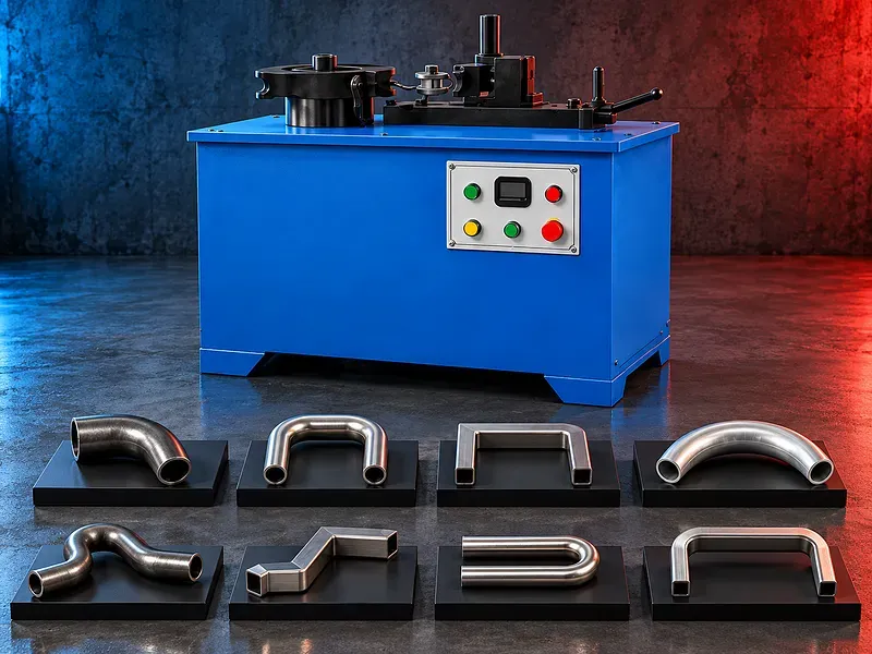
Tube bending process
The workpiece is positioned against the selected tooling and held by the clamping system while the machine applies the bending movement. Tool geometry supports the section and defines the bend path according to the chosen process.
A successful bend requires compatible material section tooling radius angle lubrication support sequence and compensation. Machine force alone does not ensure part quality.
Potential workpiece sections
Potential sections may include suitable round tube square tube rectangular tube round bar flat bar angle and selected profiles when the machine tooling and method support them.
I sections channels complex profiles and large solid sections require particular evidence because capacity deformation and tooling differ substantially from ordinary tube bending.
Materials and forming behavior
Potential materials may include supported low carbon steel stainless steel aluminum copper alloys and other ductile metals after review of grade temper hardness strength elongation surface and weld seam.
Material response affects springback cracking wrinkling ovality thinning marking and required force. A general material name does not prove bendability.
Bending methods
Rotary draw bending uses a bend die clamp die pressure die and optional internal support to form controlled bends. Compression bending wraps the workpiece around a form by moving a pressure tool.
Roll bending uses multiple rolls to create larger radii and curves. The correct method depends on section radius angle straight length quality tolerance and production pattern.
Mandrel and support tooling
A mandrel wiper die pressure die or other support may be required to control flattening wrinkling wall thinning and collapse in tight or thin wall bends.
Mandrel type ball count position lubrication extraction and clearance must match the tube and bend. Incorrect setup can mark jam split or deform the workpiece.
Clamping and positioning
The clamp should hold the workpiece against bending force without slipping crushing or excessive marking. Collets jaws pressure dies stops and supports should match the section and finish requirement.
Straight lengths grip length insertion depth seam orientation datum location and collision clearance should be defined before bending.
Bend radius angle and springback
The bend radius is measured according to the drawing convention and must be compatible with the section tooling and process. The achieved angle may differ from the commanded movement because the material springs back after unloading.
Compensation should be established through approved calculations trials and inspection. Material batch changes can require adjustment.
Automatic cycles and program control
Depending on the verified machine a program may control bend angle rotation feed length clamping sequence pressure speed and return. One touch operation may start a validated cycle but does not remove setup and inspection responsibilities.
Program storage axes data entry correction alarms recipe protection and production records are model specific and require confirmation.
Single bends and multiple bend parts
Simple parts may need one bend while frames rails furniture components and decorative work may require multiple bends with controlled straight lengths planes and orientations.
Multi bend parts require a clear datum strategy bend sequence rotation reference and collision study because one bend can restrict access for later operations.
Surface quality and dimensional inspection
Acceptance may include bend angle radius centerline geometry straight lengths leg lengths rotation between bends overall dimensions symmetry ovality flattening wall thinning wrinkles cracks marks and fit to a checking fixture.
Inspection methods should be defined from the drawing and may use templates gauges calipers angle instruments fixtures or coordinate measurement where appropriate.
Applications and production context
Potential applications include architectural rails decorative metalwork furniture frames garden structures construction components equipment guards handles supports and fabricated assemblies.
Application alone does not determine the machine. The exact profile part geometry finish structural requirement batch size and process sequence must be reviewed.
How to choose the correct machine
Provide the part drawing material grade and condition section shape dimensions wall thickness seam data bend radii angles straight lengths bend planes tolerances finish quantity batch size and target output.
Selection should consider bending method section capacity tooling system maximum bend radius or die size angle range axes clamping drive type control programs speed power lubrication loading unloading floor space and service access.
Technical information to verify
The approved exact model source must confirm manufacturer brand model bending method drive type supported sections capacity by material and conditions maximum tube or profile size wall thickness bend radius angle range axes speed repeatability and control functions.
It must also confirm hydraulic pressure or motor data clamping method tooling dimensions mandrel and wiper support lubrication electrical supply dimensions weight foundation guards safety devices included tools optional tools and environmental requirements.
Tooling change and maintenance
Tooling change should use approved lifting alignment fastening and setup methods. Die surfaces should be clean undamaged and stored to prevent corrosion or impact damage.
Preventive maintenance should cover hydraulic or mechanical drives bearings gears chains screws guides clamps mandrel mechanism lubrication controls sensors guards fasteners and periodic geometry checks according to the verified design.
Productivity and production flow
Actual productivity depends on cutting deburring cleaning marking loading positioning clamping bending rotations tool changes unloading inspection and rework rather than bend speed alone.
Batch production may benefit from validated programs dedicated tooling part supports gauges material staging and traceable first piece approval.
Safety requirements
The risk assessment should address moving bend arms rotating clamps pinch and crush zones long swinging workpieces stored hydraulic energy tooling ejection sharp edges lifting noise and electrical hazards.
Guards interlocks emergency stops restricted zones safe foot controls part supports secure tooling isolation operating instructions training personal protective equipment and maintenance controls must follow approved documentation and site requirements.
Installation and lifecycle support
Site planning should cover floor capacity anchoring leveling lifting route electrical supply grounding hydraulic oil where applicable lighting ventilation material handling long part clearance tooling storage and maintenance access.
The exact supply scope commissioning programming training tooling trial parts preventive maintenance spare parts warranty and service commitments require confirmation in the approved technical and commercial offer.
Limitations and alternative processes
A pipe and tube bender is not automatically suitable for every material section wall thickness radius angle appearance tolerance multi bend geometry duty cycle or production target.
A section roll bender press brake draw bender CNC multi axis tube bender induction bender hot bending process fabricated elbow or another method may be more suitable depending on the part.
Technical review and next step
Send the part drawing with material grade section dimensions wall thickness seam data radii angles straight lengths planes tolerances finish quantities current process and target output.
SAKKARY MACHINERY will review bending method drive and control configuration machine capacity tooling support springback compensation inspection handling safety alternatives and information that still requires manufacturer verification.
Questions we are asked
What is an automatic pipe and tube bending machine?
It is a machine that clamps and forms suitable tubes pipes profiles or bars through a controlled bending cycle using matched tooling.
Which sections can it bend?
Potential sections may include round square and rectangular tube round and flat bar angles and selected profiles when supported by the exact machine tooling material and method.
Can one tool bend different tube sizes?
Not automatically. Tool groove profile diameter radius and support must match the workpiece and approved bending method.
Why does the bend angle change after release?
The material springs back after the load is removed. Compensation depends on material section radius tooling and process conditions.
Is the machine hydraulic or mechanically driven?
The supplied description contains conflicting references to hydraulic automatic and mechanical drive or adjustment. The exact model documentation must confirm the configuration.
What information is required for selection?
Provide the drawing material grade section dimensions wall thickness seam data radii angles straight lengths planes tolerances finish quantities and target output.
Tell us the part you need to make
An engineer reads every request. Usually the same working day.
Related
- Heavy-Duty Gap-Bed Conventional Lathes Heavy-duty conventional lathes for turning large-diameter, long, and heavy rotational components. The gap-bed design provides additional swing near the headstock for suitable short workpieces.
- Gantry Type Milling Machine A gantry-type milling machine provides an open working area for machining suitable large or heavy components. Selection depends on workpiece dimensions, weight, material, required operations, tolerances, finish, and production requirements.
- Boring Machine for Workshop Machining A boring machine for drilling, enlarging, finishing, and aligning suitable holes in individual parts and small production batches. The correct model depends on workpiece size, material, hole diameter, depth, tolerance, surface finish, setup, tooling, and required output.