

FLEXIBLE INTERNAL THREADING
Arm Tapping Machines
Arm tapping machines bring a controlled tapping spindle to prepared holes across a supported work area so operators can create internal threads with less part repositioning. Electric or pneumatic configurations may improve consistency and reduce physical effort when the machine reach tap holder speed torque and process are matched to the component.
An articulated arm supports and positions the tapping head over different holes while the workpiece remains on a table fixture or assembly station. The operator aligns the tap with the prepared hole starts the cycle and controls entry depth and reversal through the functions provided by the verified machine. The correct machine depends on thread size and form workpiece material hole type hole depth required reach working height torque speed duty cycle tap and holder system lubrication workholding electrical or air supply operator access and inspection requirements.
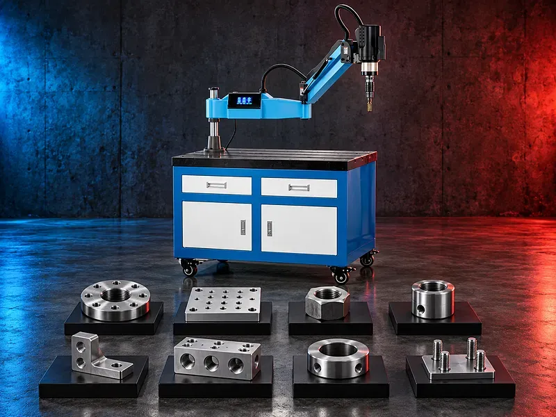
Arm tapping concept
The articulated arm allows the tapping head to move across the supported work zone and approach prepared holes without moving a large plate assembly or fixture for every position.
The arm must remain within its verified reach load and orientation limits. The tap still requires correct alignment hole preparation speed torque lubrication and reversal.
Tapping cycle
A typical cycle includes locating the hole aligning the spindle engaging the tap advancing to the controlled depth reversing withdrawing and inspecting the thread. The exact sequence depends on the drive and control arrangement.
Blind holes require depth chip space and bottom clearance control while through holes require safe exit clearance. Both need correct drill size and thread engagement.
Electric and pneumatic options
Electric tapping heads may provide programmable speed torque depth or cycle functions depending on the model. Pneumatic heads may offer simple robust operation where a suitable compressed air supply and control arrangement are available.
Drive type should be selected from verified thread range material duty control needs utilities noise maintenance and operating cost rather than preference alone.
Suitable components and applications
Potential applications include plates frames fabrications machine bases molds fixtures flanges enclosures structural components repair parts and assemblies with prepared holes inside the verified working area.
Potential users include fabrication machining maintenance assembly mold and die general engineering automotive support and production workshops after technical review of the part and thread.
Materials and thread requirements
Potential materials may include suitable steels stainless steels aluminum copper alloys cast materials and engineering plastics when the tap geometry coating lubrication speed torque and machine capability are correct.
Material grade hardness condition and chip behavior must be confirmed. A general material name does not prove that a thread size depth or production cycle is suitable.
Hole preparation
The starting hole should have the correct diameter depth straightness location entry chamfer and cleanliness for the thread standard tap type material and required thread engagement.
An undersized hole can overload or break the tap while an oversized or damaged hole can produce insufficient thread engagement. Burrs misalignment chips and poor drilling quality also affect the result.
Tap and holder selection
Tap selection should consider thread standard size pitch tolerance material hole type depth chip direction coolant or lubricant and required tool life. Spiral point spiral flute straight flute forming and other tap types serve different conditions.
The holder may provide collet retention length compensation torque control quick change or another function according to the machine. Interface size and torque range must match the tap and spindle.
Speed torque and depth control
Spindle speed torque limit feed behavior depth setting and reversal should suit the tap material thread size hole depth lubrication and supplier guidance.
Torque protection can reduce some overload risk but does not replace correct hole preparation alignment tap selection chip control or supervision. Displayed settings require validation by an approved trial.
Arm reach and working position
Selection should consider horizontal reach minimum and maximum working radius vertical movement head articulation working height table or column mounting and access around the component.
Part height fixture height nearby obstacles hole orientation operator stance and safe withdrawal can reduce the practical work area. Some models may support vertical or horizontal tapping through an approved head arrangement.
Workholding and alignment
The workpiece should be supported against tapping torque and spindle reaction without movement distortion or unsafe manual restraint. Tables fixtures clamps stops and supports should suit the component and hole locations.
The tapping head must be aligned with the prepared hole to avoid cross threading tap bending uneven loading poor thread form or breakage.
Thread quality and inspection
Acceptance may include thread size pitch class depth position perpendicularity entry condition and functional fit with the mating component according to the drawing and thread standard.
Inspection may use approved plug gauges depth methods optical checks or mating parts as appropriate. Gauges should be identified calibrated and used under controlled conditions.
Productivity and operator effort
Moving the tapping head instead of repeatedly repositioning a large workpiece can reduce handling and support a smoother sequence across multiple holes. Balanced arm support may also reduce lifting effort.
Actual productivity depends on part layout thread sizes hole quality tool changes lubrication handling inspection and operator method. Increased output or reduced fatigue should be verified for the real application.
How to choose the correct machine
Provide the component drawing material hardness thread standard sizes pitches hole types depths quantities hole layout part dimensions weight fixture arrangement duty cycle and target output.
Selection should consider tapping range torque speed reach vertical travel head orientation holder system depth control drive type mounting table lubrication electrical or air supply guards accessories floor space and service access.
Technical information to verify
The approved exact model source must confirm manufacturer brand model drive type tapping capacity by material and conditions torque range speed range reach working radius vertical movement head orientation holder interface depth control and duty rating.
It must also confirm table or column dimensions mounting loads electrical supply or air pressure and consumption controls lubrication dimensions weight guards safety devices included collets or holders optional equipment and environmental requirements.
Safety requirements
The risk assessment should address rotating taps and holders entanglement tap breakage sharp chips workpiece movement arm movement pinch points stored pneumatic energy lubricants manual handling and electrical hazards.
Secure workholding correct tooling guards emergency stops safe alignment operating instructions training personal protective equipment isolation and maintenance controls must follow approved documentation and site requirements.
Installation maintenance and support
Site planning should cover a rigid mounting surface stable table or base reach clearance electrical supply or clean regulated compressed air grounding lighting lubrication chip management operator access and maintenance space.
Preventive maintenance should cover arm joints bearings balance system spindle drive collets holders controls air preparation where fitted cables hoses lubrication mounting fasteners and safety devices. Supply scope training spare parts warranty and service commitments require approved confirmation.
Limitations and alternative processes
An arm tapping machine is not automatically suitable for every thread material diameter pitch depth orientation tolerance duty cycle or output target. Very small large deep hard interrupted or high precision threads may need another process.
A drill press tapping head milling machine CNC machining center dedicated tapping center thread milling roll forming or manual method may be more suitable depending on the component and production requirement.
Technical review and next step
Send the part drawing with material hardness thread standard sizes pitches hole types depths layout quantities fixture method current process utilities and target output.
SAKKARY MACHINERY will review tap type machine reach speed torque holder lubrication workholding inspection utilities safety alternative processes and information that still requires manufacturer verification.
Questions we are asked
What is an arm tapping machine?
It is a threading machine with an articulated arm that positions a tapping head over prepared holes across a supported work area.
Why use an articulated arm?
The arm moves the tapping head between hole positions and can reduce repeated handling of large plates fixtures or assemblies.
Can the machine tap metal and plastic?
Potentially yes but suitability depends on the exact material thread size hole condition tap lubrication speed torque and machine capability.
What is the difference between electric and pneumatic tapping?
Electric systems may provide programmable control functions while pneumatic systems require suitable clean regulated air. Exact behavior depends on the verified model.
Does torque control prevent tap breakage?
It can reduce some overload risk but cannot replace correct hole preparation alignment tap selection lubrication chip control and operation.
What information is required for selection?
Provide the drawing material hardness thread standard sizes pitches hole types depths layout quantities fixture method and target output.
Tell us the part you need to make
An engineer reads every request. Usually the same working day.
Related
- Heavy-Duty Gap-Bed Conventional Lathes Heavy-duty conventional lathes for turning large-diameter, long, and heavy rotational components. The gap-bed design provides additional swing near the headstock for suitable short workpieces.
- Gantry Type Milling Machine A gantry-type milling machine provides an open working area for machining suitable large or heavy components. Selection depends on workpiece dimensions, weight, material, required operations, tolerances, finish, and production requirements.
- Boring Machine for Workshop Machining A boring machine for drilling, enlarging, finishing, and aligning suitable holes in individual parts and small production batches. The correct model depends on workpiece size, material, hole diameter, depth, tolerance, surface finish, setup, tooling, and required output.