

DUCT FLANGE AND CLIP FORMING
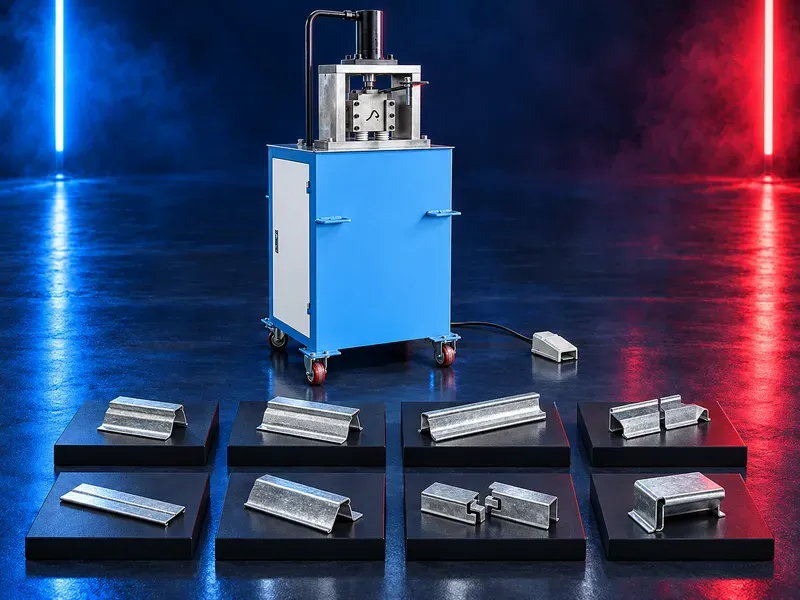
TDF Flange and Clip Forming Machine for HVAC Ducts
A TDF flange forming machine progressively forms an integral flange along one selected edge of a rectangular duct blank. Depending on the verified roll configuration the opposite forming side may produce a compatible clip profile for duct assembly.
The sheet blank is guided through powered forming rolls that shape the edge in stages until the approved TDF profile is completed. Stable feeding alignment and correct roll setup help maintain flange straightness and consistent fit. The machine can work as a separate workshop or site unit within a rectangular duct production process that also includes cutting beading notching folding lock forming seam closing and clip preparation as required. Claims for large duct suitability low production cost high installation efficiency mobility exact material range and service support require confirmation from the approved machine data sheet factory layout and representative sample trials.
What the machine does
The machine forms a TDF connection edge directly from the duct sheet. One forming route produces the flange while another route may produce a clip profile when included in the verified tooling package.
The result depends on sheet condition entry alignment roll geometry drive stability and inspection.
TDF flange forming
The TDF profile creates an integral duct connection for later corner fitting sealing fastening and assembly. Progressive roll stages control the edge shape without a separate attached flange.
Flange height shape straightness and corner details must match the approved duct standard and assembly accessories.
Clip profile forming
A dedicated forming route may produce clips used to secure mating TDF flanges. The actual clip geometry width and material must match the flange thickness and closing method.
Confirm whether clip forming is standard optional or requires separate tooling and how finished clips are cut handled and stored.
Single machine arrangement
Unlike a duplex machine that forms two flange edges together this arrangement normally processes one flange edge at a time while the opposite roll route may be assigned to clip production.
Choose between single and duplex solutions from blank sizes production mix changeovers floor space mobility and required output.
Sheet feeding and support
Entry guides and supports should keep the sheet level and aligned as powered rolls pull it through the forming stages. Long or wide blanks may need additional infeed and outfeed support.
Verify feeding direction minimum and maximum blank dimensions support height and handling rules for flexible or finished surfaces.
Forming rolls and drive
Roll geometry hardness finish alignment and bearing condition affect the final flange and clip profiles. The drive must provide stable movement without slipping or marking the sheet.
Verify roll material heat treatment drive power transmission lubrication wear limits setup gauges replacement method and spare roll availability.
Materials and sheet condition
Provide sheet grade coating thickness width hardness surface finish and protective requirements. Galvanized sheet stainless steel aluminium or other materials require separate confirmation for roll design power speed lubrication and surface protection.
Do not assume compatibility from material name alone because grade hardness thickness and coating affect forming behavior.
Rectangular duct applications
The machine prepares connection edges for rectangular ventilation and air conditioning duct sections. It may be used for standard batches varied workshop orders or site work when the working envelope and handling method are suitable.
Large section duct claims require confirmation of sheet support blank dimensions stiffness operator handling and downstream folding capacity.
Mobility and site use
Some configurations may include wheels or a compact frame for movement between workshop areas or installation sites. Mobility does not replace the need for stable positioning and safe utilities during operation.
Confirm machine weight wheel rating brakes anchoring lifting points route clearances cable protection and the level surface required for forming.
Integration in a duct workshop
The machine may work with cutting beading notching folding lock forming seam closing and clip cutting equipment. A clear material flow reduces unnecessary turning lifting and damage to formed edges.
Define which operation establishes the reference dimension and how blanks and clips are identified and transferred to final assembly.
Productivity and labor
Actual output depends on blank length thickness loading support forming speed changeovers clip cutting and the capacity of upstream and downstream operations.
Measure accepted flanged blanks and usable clips per shift during representative trials instead of relying on general cost or labor saving claims.
Quality control
Acceptance should cover flange height shape straightness edge condition surface marking clip fit corner fit and compatibility with seals fasteners and mating duct sections.
Inspect the first piece after roll adjustment material change relocation or maintenance using approved gauges and calibrated equipment.
Common process risks
Misalignment worn rolls unsuitable thickness unstable support or incorrect feeding can cause waviness twist incomplete profiles scratches or poor clip engagement.
Correct the setup when the flange or clip falls outside the approved drawing rather than compensating during installation.
Safety and operator protection
The machine contains powered rolls pinch points rotating transmission parts and sharp sheet edges. Guards emergency stops safe feeding tools and controlled access should follow the approved risk assessment.
Safe procedures must cover loading trial forming unloading clip handling jam recovery cleaning lubrication relocation and maintenance.
Installation and site readiness
Site preparation should confirm level floor electrical supply required compressed air infeed and outfeed clearance lighting and service access.
For site operation protect power connections control exposure weather conditions sheet storage and movement routes.
Training maintenance and lifecycle support
Training should cover safe feeding roll inspection flange and clip gauges material change jam recovery relocation and daily care.
Preventive maintenance should address rolls bearings gears chains shafts guides drives guards fasteners lubrication electrical controls and emergency devices. Prepare approved spare parts and consumables.
How to select the correct machine
Start with duct standards flange and clip geometry sheet materials thickness range blank dimensions production mix shift target surface requirements mobility and downstream folding sealing and assembly methods.
Selection should confirm tooling drive utilities working envelope site conditions integration service support and representative sample trials.
Technical information requiring verification
Verify material types thickness range working width blank dimensions flange and clip profiles forming speed drive power roll material accuracy utilities electrical load compressed air mobility dimensions and total weight.
Confirm large duct capability stainless steel capability optional tooling guards installation commissioning training warranty service scope spare parts and acceptance tests from approved documentation.
Publishing status
This page describes the machine category process and selection logic. Exact thickness width speed output materials flange and clip dimensions mobility options standards and commercial commitments require an approved data sheet and technical review before publication.
Questions we are asked
What is a TDF flange forming machine?
It is a roll forming machine that creates an integral TDF connection flange along an approved sheet metal duct edge.
Can the machine also form clips?
A second forming route may produce compatible clips when the required rolls and cutting method are included and verified.
What is the difference between single and duplex machines?
A single arrangement normally forms one flange edge per pass while a duplex arrangement can form two selected flange edges together.
Is the machine suitable for site work?
Site use depends on verified mobility weight utilities stable positioning environmental protection and safe sheet handling.
How is flange quality checked?
Check flange height shape straightness surface condition corner fit clip engagement and compatibility with approved seals and fasteners.
What information is needed for selection?
Provide duct standard flange and clip geometry materials thickness range blank dimensions quantities mobility needs downstream equipment utilities and layout.
Tell us the part you need to make
An engineer reads every request. Usually the same working day.
Related
- Spiral Duct Forming Machine A forming machine for producing round spiral air ducts from compatible metal strip. Machine selection depends on duct diameter, material, strip thickness and width, seam type, cut length, and production target.
- U Shape Automatic Duct Production Line A U shape automatic duct production line converts approved sheet metal coils into prepared duct sections through a coordinated sequence that may include uncoiling leveling beading punching shearing locking flange forming and folding. The correct configuration depends on duct type material thickness dimensions flange system output target and factory layout.
- Automatic Duct Production Line for Rectangular HVAC Ducts An automatic duct production line converts approved sheet metal coils into prepared rectangular HVAC duct blanks and folded sections through a coordinated linear workflow. Depending on the verified configuration it may integrate uncoiling leveling beading punching shearing transfer locking flange forming and folding